


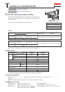

P 6/ 7
Repair
[3] DISASSEMBLY/ASSEMBLY
[3] -5. Motor Section (cont.)
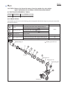
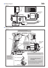
Fig. 16
ASSEMBLING
[3] -6. Switch
3) Assemble the Motor section to Housing L as illustrated in Fig. 16.
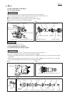
Put the projection on Switch between the prongs of F/R change lever,
then assemble the Switch to Housing L. (Fig. 17)
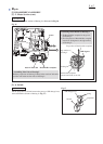
notch in Yoke unit Brush holder complete
groove
Housing L
rib
ASSEMBLING
With the projection on Housing L fitting in the notch on Yoke unit,
put Yoke unit inside the four ribs on Housing L.
Fig. 17
F/R change lever
Switch
projection
prong
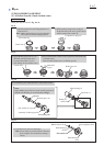
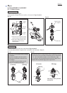
1) Fit Brush holder complete in the groove
of Housing L.
2) The flat portion of Brush holder complete
must be at 90 degrees to the edge surface
of Housing L.
flat portion of Brush holder complete
edge surface of
Housing L
Housing L
Brush holder complete
viewed from Front cover side
90 degrees
Assembling Brush Holder to Housing L
projection
Assembling Yoke Unit to Housing L