


P 11/ 17
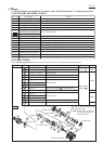
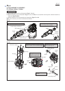
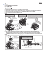
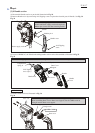
Assemble Cylinder guide to Cylinder 32 so that O ring 46
side of Cylinder guide faces Crank housing side.
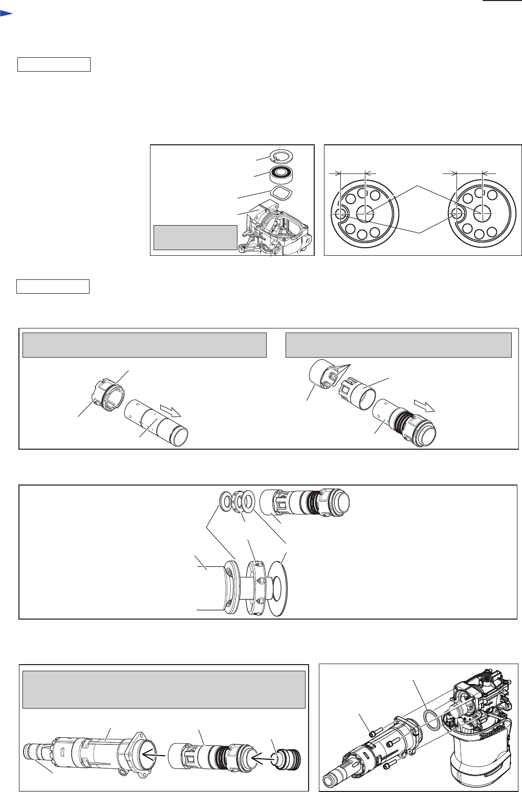
(1) Cylinder section can be assembled as illustrated in Fig. 25.
Cylinder guide
Cylinder 32
O ring 46
Crank housing
Side
Crank housing
side
Align the six protrusions of Guide ring to Slide sleeve
and assemble Guide ring to Slide sleeve.
Guide ring
Slide sleeve
Cylinder 32
Six protrusions
[3]-6 Cylinder section
Fig. 25
Repair
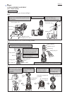
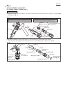
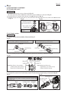
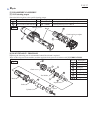
(2) When assembling the parts which accept Impact bolt, put them into Guide ring as illustrated in Fig. 26.
(3) Assemble Cylinder section to Barrel as illustrated in Fig. 27.
(4) Assemble Flat washer 34 into Crank housing, and then assemble Barrel to Crank housing as illustrated in Fig. 28.
Fig. 26
Fig. 27 Fig. 28
Impact bolt
Ring 20
Note: Ring 20 has to be assembled
so that its inner side can be fit to
Impact bolt as illustrated right.
Note: Rubber ring 20 has to be
assembled so as to contact closely
to Ring 20 without any gap.
Rubber
ring 20
Flat washer 23
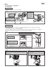
Tool holder
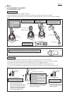
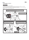
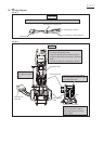
Insert Cylinder section into Barrel.
Insert Striker into the Cylinder so that the protrusion of Striker faces
Tool holder side.
Flat washer 34
Guide ring
M6x25 Hex socket
head bolt (4pcs.)
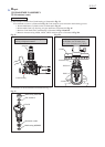
ASSEMBLING
ASSEMBLING
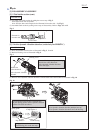
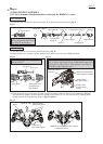
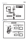
(1) Assemble Crank housing section as illustrated in Fig.s 23.
Be careful that Crank shaft of HM0870C is different from that of HM0871Cas illustrated in Fig. 24.
(2) Assemble Piston to Crank pin while referring to the right illustration in Fig. 16.
(3) Assemble Air pipe, Seal ring and Crank cap. And secure them with M4x18 Pan head screws. Refer to the left illustration
in Fig. 16.
Retaining ring R-40
Set the above parts
in place.
Ball bearing 6203LLU
Wave washer 30
Crank housing
Fig. 23
Fig. 24
HM0871CHM0870C
17.5mm
Center of
Crank shaft
Center of
Crank pin
17mm
[3] DISASSEMBLY/ASSEMBLY
[3]-5 Crank shaft (cont.)
Protrusion
of Striker
Cylinder sectionBarrel