


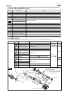
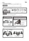
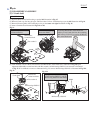
Wiring diagram
P 17/ 17
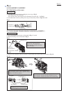
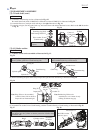
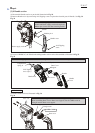
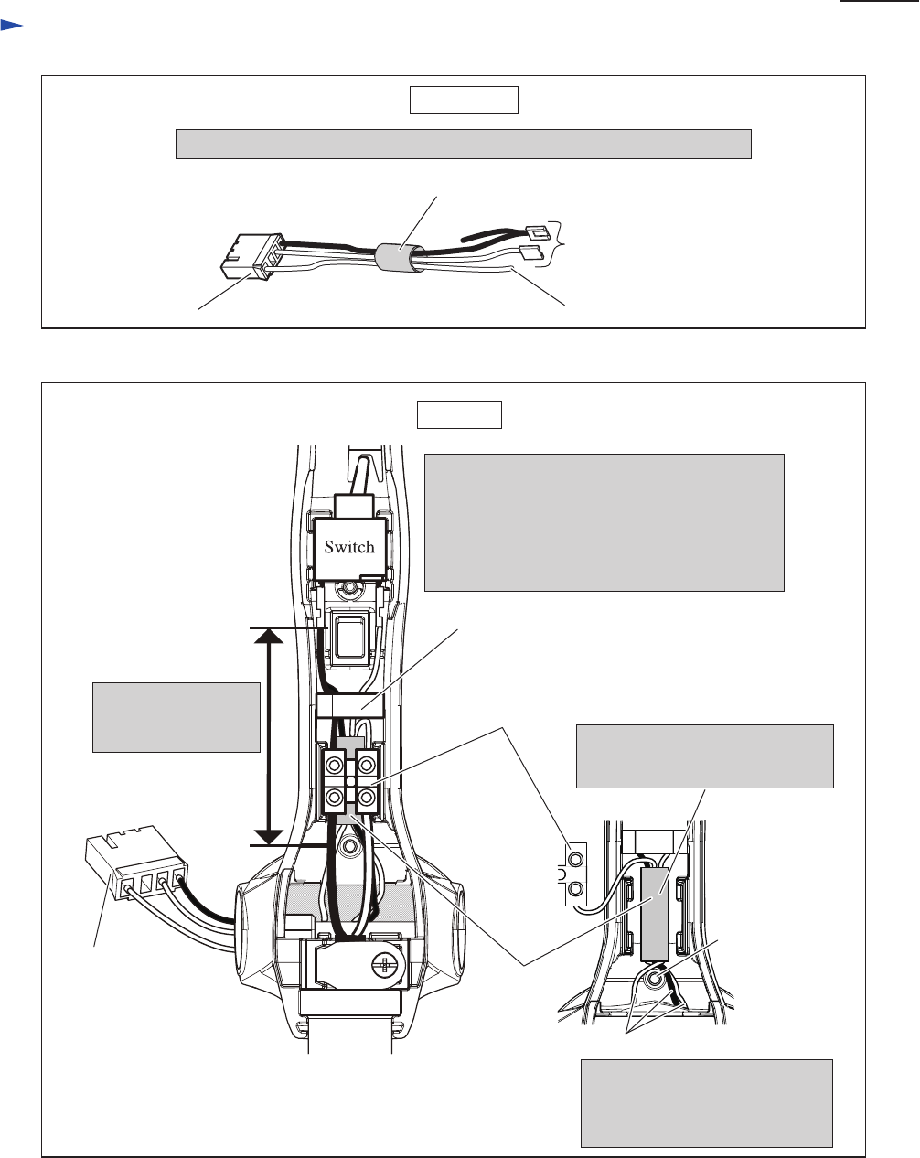
Fig. D-3
Handle
Lead Unit
Fig. D-4
Polyethylene Tube Ø8-30
Connector
for connecting to Switch
for connecting to Terminal block
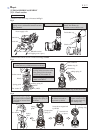
Pass the Lead wires of Lead unit through Polyethylene tube illustrated below.
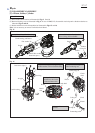
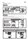
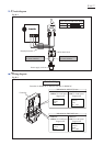
Lead unit’s Lead wires
Lead unit’s Lead wires have to
be put on both side of Boss,
And connect them to Switch
and Terminal.
Lead unit’s Lead wires bundled
with Polyethylene tube has to put
under Terminal block.
Boss
Terminal block
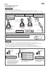
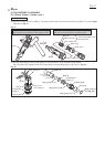
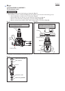
Sponge sheet
Connector of
Lead unit
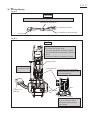
Put the following Lead wires
of Lead unit into Sponge sheet.
* Lead wire (black) for connecting to Switch
* Lead wire (black) for connecting to Terminal
block
* Lead wire (white) for connecting to Switch
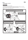
The Lead wires have
to be tightened in this
area.
Polyethylene
tube