DISASSEMBLING
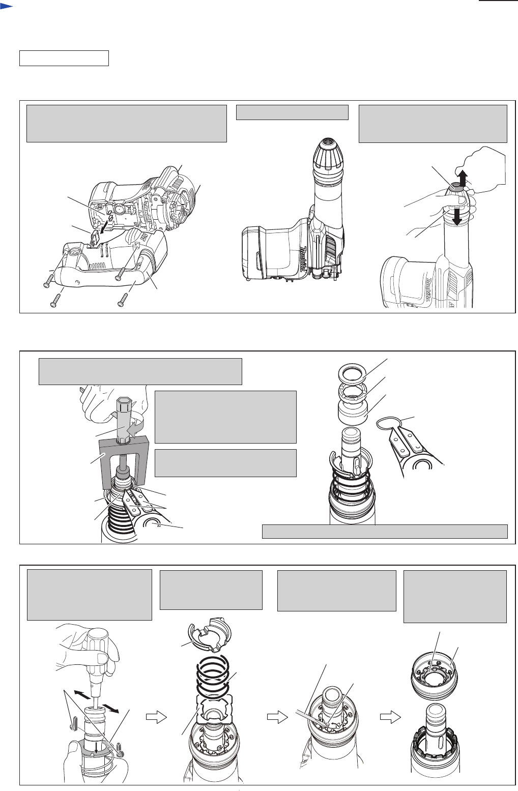
(1) Remove Tool holder cap as illustrated in Fig. 2.
Remove Handle section by loosening four 5x25
Tapping screws, and then disconnect Lead unit
from Controller.
Stand the machine upright. While pressing down Chuck cover,
remove Tool holder cap.
And then, remove Chuck cover.
Fig. 2
Handle section
Lead unit
Controller
Note: It is not necessary to disconnect Switch and
Power supply cord.
Chuck cover
Tool holder cap
P 3/ 17
Repair
[3] DISASSEMBLY/ASSEMBLY
[3]-1. Chuck section
(2) Disassemble Chuck section as illustrated in Figs. 3 and 4.
2. Press down Flat washer 28 by
turning Socket wrench to make
Ring spring 25 free from the
pressure by Flat washer 28.
3. Remove Ring spring 25 using
1R003 with 1R212.
4. Remove Flat washer 28, Rubber ring 28 and Chuck ring.
Remove Spring guide,
Compression spring 52
and Plate.
Remove four Steel balls 4.8
with Slotted screwdriver
magnetized by 1R288.
Remove Change ring
together with Lock ring.
And separate Lock ring
from Change ring.
While pressing down Spring
guide, push out Tool retainers
by screwdriver inserted from
Tool holder.
Fig. 3
Fig. 4
Flat washer 28
1R003
Flat washer 28
1R363
1. Pulling down Chuck cover, install 1R363
in the same way of SDS-MAX bit installation.
Socket wrench
Spring guide
Ring spring 25
Ring spring 25
Rubber ring 28
Chuck ring
Tool retainer
Spring
guide
Spring
guide
Plate
Compression
spring 52
Steel ball 4.8
(4pcs.)
Screwdriver magnetized
by 1R288
Lock ring
Change ring
5x25 Tapping screw (4pcs.)
1R212


