


6
ENGLISH (Original instructions)
Explanation of general view
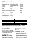
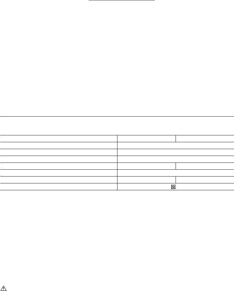
SPECIFICATIONS
• Due to our continuing program of research and development, the specifications herein are subject to change without
notice.
• Specifications may differ from country to country.
• Weight according to EPTA-Procedure 01/2003
Intended use
ENE001-1
The tool is intended for planing wood.
Power supply
ENF002-2
The tool should be connected only to a power supply of
the same voltage as indicated on the nameplate, and can
only be operated on single-phase AC supply. They are
double-insulated and can, therefore, also be used from
sockets without earth wire.
General Power Tool Safety
Warnings GEA010-1
WARNING Read all safety warnings and all
instructions. Failure to follow the warnings and
instructions may result in electric shock, fire and/or
serious injury.
Save all warnings and
instructions for future reference.
PLANER SAFETY WARNINGS
GEB010-5
1. Wait for the cutter to stop before setting the tool
down. An exposed rotating cutter may engage the
surface leading to possible loss of control and serious
injury.
2. Hold the power tool by insulated gripping surfaces
only, because the cutter may contact its own cord.
Cutting a “live” wire may make exposed metal parts of
the power tool “live” and could give the operator an
electric shock.
3. Use clamps or another practical way to secure and
support the workpiece to a stable platform. Holding
the work by your hand or against the body leaves it
unstable and may lead to loss of control.
4. Rags, cloth, cord, string and the like should never
be left around the work area.
5. Avoid cutting nails. Inspect for and remove all
nails from the workpiece before operation.
6. Use only sharp blades. Handle the blades very
carefully.
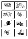
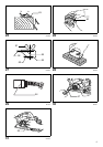
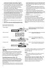
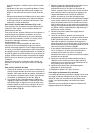
1. Knob
2. Pointer
3. Lock button / Lock-off button
4. Switch trigger
5. Planer blade
6. Rear base
7. Foot
8. Socket wrench
9. Bolts
10. Drum
11. Drum cover
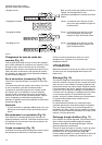
12. Adjusting plate
13. Inside edge of gauge plate
14. Blade edge
15. Screws
16. Heel
17. Back side of gauge base
18. Gauge plate
19. Gauge base
20. Pan head screw
21. Planer blade locating lugs
22. Heel of adjusting plate
23. Set plate
24. Inside flank of gauge plate
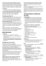
25. Back side of gauge base
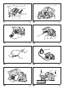
26. Mini planer blade
27. Groove
28. Set plate
29. Hex. flange head bolts
30. Stopper
31. Chip discharge opening
32. Recessed part
33. Protrusion
34. Dust bag
35. Fastener
36. Vacuum cleaner
37. Elbow
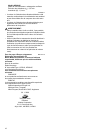
38. Start
39. End
40. Cutting line
41. Depth guide
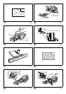
42. Screw (A)
43. Screw (B)
44. Edge fence
45. V groove (medium amount of
chamfering)
46. V groove (small amount of
chamfering)
47. V groove (great amount of
chamfering)
48. Chamfering rule
49. Edge of chamfering rule
50. Sharpening holder
51. Wing nut
52. Blade (A)
53. Blade (B)
54. Side (D)
55. Side (C)
56. Limit mark
57. Screwdriver
58. Rear cover
59. Carbon brushes
Model KP0810 KP0810C
Planing width 82 mm
Planing depth 4 mm
Shiplapping depth 25 mm
No load speed (min
-1
) 16,000 12,000
Overall length 290 mm
Net weight 3.3 kg 3.4 kg
Safety class /II