


15
and while holding the workpiece from moving, move
the set plate flush against the end of the workpiece.
Then secure the set plate with the screw. When the
set plate is not used, loosen the screw and turn the
set plate out of the way.
NOTE:
• Use of the holder-rod assembly (optional
accessory) allows cutting repetitive lengths up to
2,200 mm (7.2 ft.) approximately.
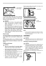
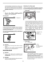
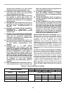
Carrying tool
Make sure that the tool is unplugged. Secure the blade at
0° bevel angle and the turn base at left miter angle fully.
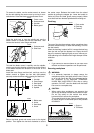
Lower the handle fully and lock it in the lowered position
by pushing in the stopper pin.
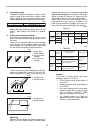
Carry the tool by carrying grip as shown in the figure. If
you remove the holders, dust bag, etc., you can carry the
tool more easily.
CAUTION:
• Always secure all moving portions before carrying
the tool.
• Stopper pin is for carrying and storage purposes
only and not for any cutting operations.
MAINTENANCE
CAUTION:
• Always be sure that the tool is switched off and
unplugged before attempting to perform inspection
or maintenance.
WARNING:
• Always be sure that the blade is sharp and clean for
the best and safest performance.
Adjusting the cutting angle
This tool is carefully adjusted and aligned at the factory,
but rough handling may have affected the alignment. If
your tool is not aligned properly, perform the following:
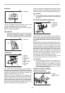
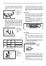
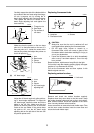
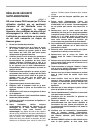
1. Miter angle.
Loosen the grip which secures the turn base. Turn
the turn base so that the pointer points to 0° on the
miter scale. Tighten the grip and loosen the hex
bolts securing the guide fence using the socket
wrench.
Lower the handle fully and lock it in the lowered
position by pushing in the stopper pin. Square the
side of the blade with the face of the guide fence
using a triangular rule, try-square, etc. Then
securely tighten the hex bolts on the guide fence in
the order from the right side.
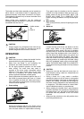
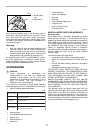
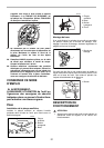
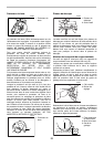
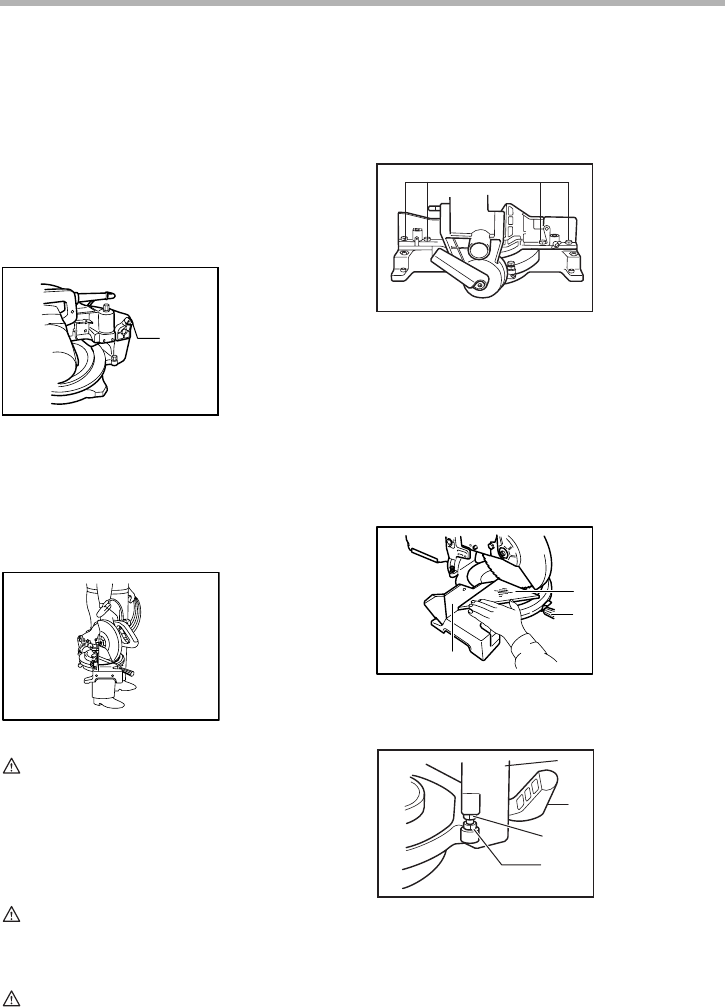
2. Bevel angle
(1) 0° bevel angle
Lower the handle fully and lock it in the low-
ered position by pushing in the stopper pin.
Loosen the lever at the rear of the tool.
Loosen the hex nut and turn the 0° bevel
angle adjusting bolt on the right side of the
arm two or three revolutions clockwise to tilt
the blade to the right.
1. Stopper pin
1
001792
003833
1. Hex bolt
1. Triangular rule
2. Grip
3. Guide fence
1. Arm
2. Lever
3. 0° adjusting bolt
4. Hex nut
1
002258
3
1
2
002259
2
4
3
1
001768