


16
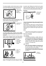
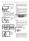
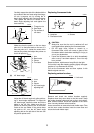
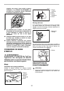
Carefully square the side of the blade with the
top surface of the turn base using the triangu-
lar rule, try-square, etc. by turning the 0°
bevel angle adjusting bolt counterclockwise.
Then tighten the hex nut to secure the 0°
bevel angle adjusting bolt and tighten the
lever securely.
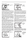
Make sure that the pointer on the turn base
point to 0° on the bevel scale on the arm. If it
does not point to 0°, loosen the screw which
secures the pointer and adjust the pointer so
that it will point to 0°.
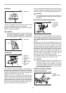
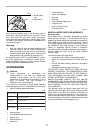
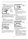
(2) 45° bevel angle
Adjust the 45° bevel angle only after perform-
ing 0° bevel angle adjustment. To adjust left
45° bevel angle, loosen the lever and tilt the
blade to the left fully. Make sure that the
pointer on the arm points to 45° on the bevel
scale on the arm holder. If the pointer does
not point to 45°, turn the 45° bevel angle
adjusting bolt on the left side of the arm until
the pointer points to 45°.
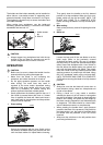
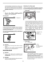
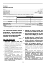
Replacing fluorescent tube
CAUTION:
• Always be sure that the tool is switched off and
unplugged before replacing the fluorescent tube.
• Do not apply force, impact or scratch to a
fluorescent tube, which can cause a glass of the
fluorescent tube to be broken resulting in a injury to
you or your bystanders.
• Leave the florescent tube for a while immediately
after a use of it and then replace it. If not. You may
burn yourself.
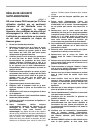
Remove screws, which secure Lamp Box for the light.
Pull out the Lamp Box keeping pushing lightly the upper
position of it as illustrated on the left.
Pull out the fluorescent tube and then replace it with
Makita original new one.
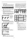
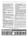
Replacing carbon brushes
Remove and check the carbon brushes regularly.
Replace when they wear down to the limit mark. Keep
the carbon brushes clean and free to slip in the holders.
Both carbon brushes should be replaced at the same
time. Use only identical carbon brushes.
Use a screwdriver to remove the brush holder caps. Take
out the worn carbon brushes, insert the new ones and
secure the brush holder caps.
1. Triangular rule
2. Saw blade
3. Top surface of
turn base
1. Arm
2. Bevel scale
3. Pointer
4. Turn base
1. Lever
2. Arm
3. Pointer
4. 45° bevel angle
adjusting bolt
1
2
3
001819
12
3
4
001769
1
2
3
4
001770
1. Pull out 2. Push
3. Lamp box 4. Screws
5. Fluorescent tube
1. Limit mark
1
2
3
4
1
5
002028
1
001145