


9
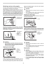
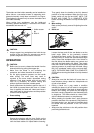
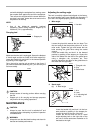
Sub-fence
This tool is equipped with the sub-fence which should
ordinarily be positioned as shown in the figure.
However, when performing left bevel cuts, set it to the left
position as shown in the figure.
CAUTION:
• When performing left bevel cuts, flip the fence over
to the left position as shown in the figure.
Otherwise, it will contact the blade or a part of the
tool, causing possible serious injury to the operator.
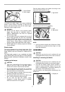
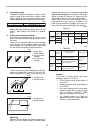
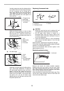
Vertical vise
The vertical vise can be installed in two positions on
either the left or right side of the guide fence or the holder
assembly (optional accessory). Insert the vise rod into
the hole in the guide fence or the holder assembly and
tighten the screw to secure the vise rod.
Position the vise arm according to the thickness and
shape of the workpiece and secure the vise arm by tight-
ening the screw. If the screw to secure the vise arm con-
tacts the guide fence, install the screw on the opposite
side of vise arm. Make sure that no part of the tool con-
tacts the vise when lowering the handle all the way. If
some part contacts the vise, re-position the vise.
Press the workpiece flat against the guide fence and the
turn base. Position the workpiece at the desired cutting
position and secure it firmly by tightening the vise knob.
CAUTION:
• The workpiece must be secured firmly against the
turn base and guide fence with the vise during all
operations.
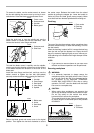
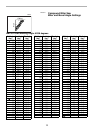
Horizontal vise (optional accessory)
The horizontal vise can be installed in two positions on
either the left or right side of the base. When performing
15° or greater miter cuts, install the horizontal vise on the
side opposite the direction in which the turn base is to be
turned.
By turning the vise knob counterclockwise, the screw is
released and the vise shaft can be moved rapidly in and
out. By turning the vise knob clockwise, the screw
remains secured. To grip the workpiece, turn the vise
knob gently clockwise until the projection reaches its top-
most position, then fasten securely. If the vise knob is
forced in or pulled out while being turned clockwise, the
projection may stop at an angle. In this case, turn the
vise knob back counterclockwise until the screw is
released, before turning again gently clockwise.
The maximum width of the workpiece which can be
secured by the horizontal vise is 130 mm (5-1/8”).
CAUTION:
• Grip the workpiece only when the projection is at
the topmost position. Failure to do so may result in
insufficient securing of the workpiece. This could
cause the workpiece to be thrown, cause damage
to the blade or cause the loss of control, which can
result in PERSONAL INJURY.
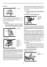
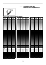
Holders and holder assembly
(optional accessories)
1. Sub-fence
1. Sub-fence
1. Vise arm
2. Vise rod
3. Guide fence
4. Holder
5. Holder assem-
bly
6. Vise knob
7. Screw
1
001766
1
001767
1
2
3
6
4
57
001796
1. Vise knob
2. Projection
3. Vise shaft
4. Base
1. Holder
2. Holder assem-
bly
12
3
4
001807
12
002247