


6
Maintaining maximum cutting capacity
This tool is factory adjusted to provide the maximum cut-
ting capacity for a 255 mm (10”) saw blade.
When installing a new blade, always check the lower limit
position of the blade and if necessary, adjust it as follows:
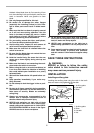
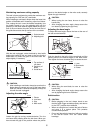
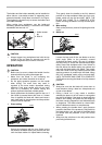
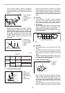
First, unplug the tool. Lower the handle completely. Use
the socket wrench to turn the adjusting bolt until the
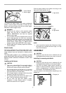
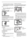
periphery of the blade extends slightly below the top sur-
face of the turn base at the point where the front face of
the guide fence meets the top surface of the turn base.
With the tool unplugged, rotate the blade by hand while
holding the handle all the way down to be sure that the
blade does not contact any part of the lower base. Re-
adjust slightly, if necessary.
CAUTION:
• After installing a new blade, always be sure that the
blade does not contact any part of the lower base
when the handle is lowered completely. Always do
this with the tool unplugged.
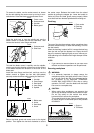
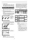
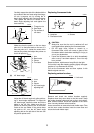
Adjusting the miter angle
Loosen the grip by turning counterclockwise. Turn the
turn base while pressing down the lock lever. When you
have moved the grip to the position where the pointer
points to the desired angle on the miter scale, securely
tighten the grip clockwise.
CAUTION:
• When turning the turn base, be sure to raise the
handle fully.
• After changing the miter angle, always secure the
turn base by tightening the grip firmly.
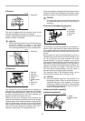
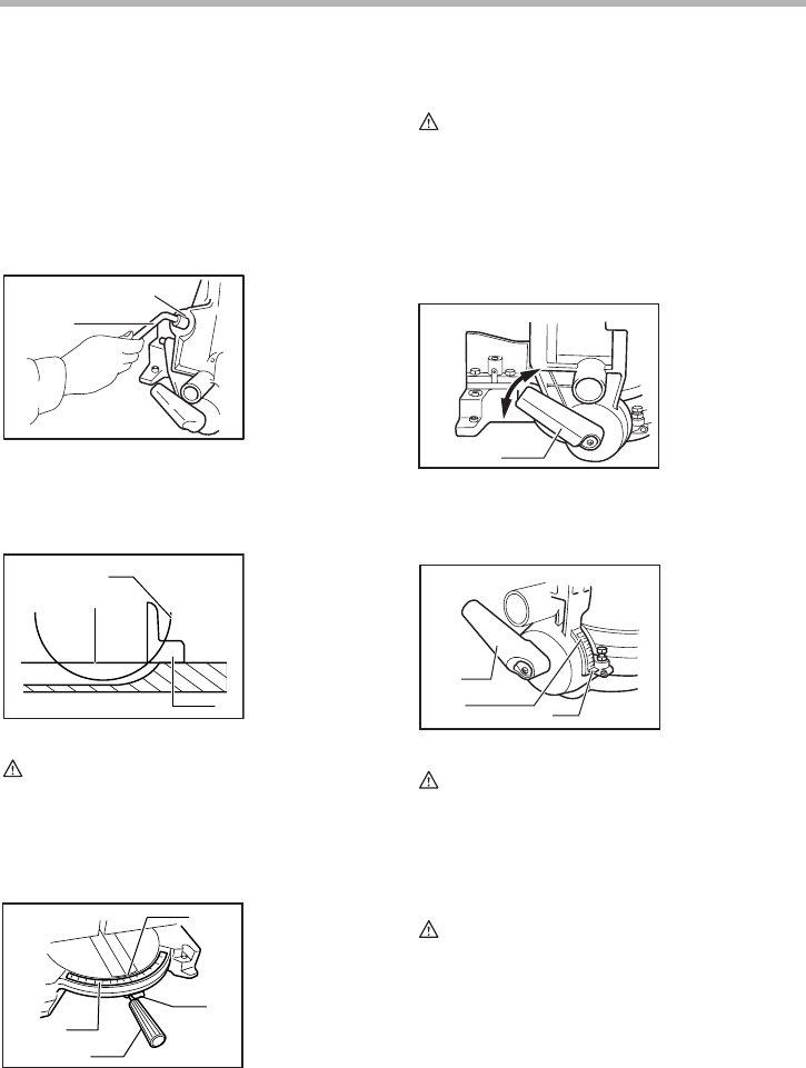
Adjusting the bevel angle
To adjust the bevel angle, loosen the lever at the rear of
the tool counterclockwise.
Push the handle to the left to tilt the saw blade until the
pointer points to the desired angle on the bevel scale.
Then tighten the lever clockwise firmly to secure the arm.
CAUTION:
• When tilting the saw blade, be sure to raise the
handle fully.
• After changing the bevel angle, always secure the
arm by tightening the lever clockwise.
Switch action
CAUTION:
• Before plugging in the tool, always check to see
that the switch trigger actuates properly and returns
to the “OFF” position when released.
• When not using the tool, remove the lock-off button
and store it in a secure place. This prevents
unauthorized operation.
• Do not pull the switch trigger hard without pressing
in the lock-off button. This can cause switch
breakage.
1. Socket wrench
2. Adjusting bolt
1. Top surface of
turn base
2. Periphery of
blade
3. Guide fence
1. Pointer
2. Lock lever
3. Grip
4. Miter scale
1
2
002257
2
1
3
001540
1
2
3
4
001778
1. Lever
1. Lever
2. Bevel scale
3. Pointer
1
001864
1
2
3
001865