


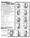
Page 27
Makita 3612
Series
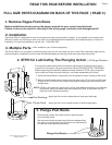
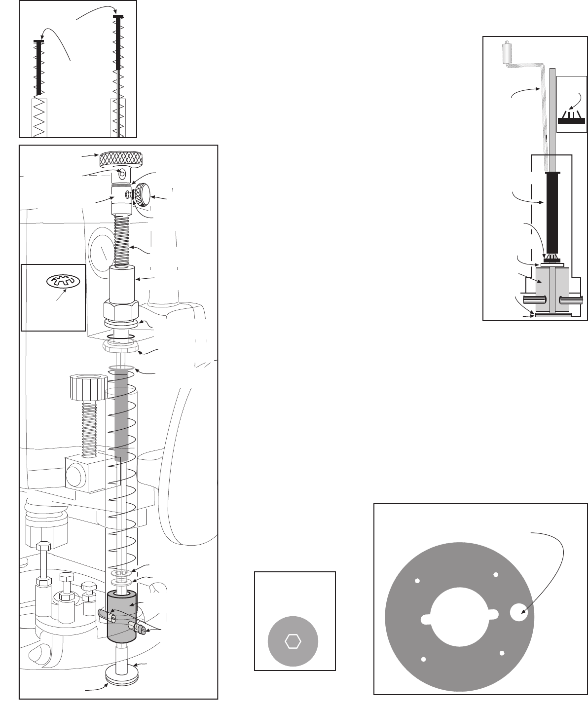
fig 11
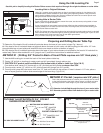
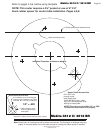
Locate raizer access point on original subbase.
Drill a 3/4" hole through subbase
Access hole Drill 3/4"
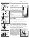
Reassembling Router ( Plunge Springs Must be Installed )
1. Stand base upright, using ( fig 8 ) replace both plunge springs. Place #13 hollow
spring guide in the top of #1 mainshaft spring. Place original steel spring guide in
top of other spring. Caution: Do not assemble router without plunge springs and
guides Installed.
2. Unlock plunge lock. Grasp router handles and guide spring into motor housing.
Slowly lower the motor housing. Aligning #1 mainshaft through #19 short drive
nut. Plunge the router and engage plunge lock.
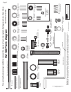
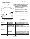
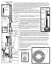
6. Select #1 mainshaft, #7 brass washer, #13 hollow spring guide #14, 3/16"steel washer, #15 one retainer,
#29 speed wrench. Cut #1 mainshaft to 10 1/8" overall length, and debur cut end. Using ( fig 7 ) Grease
both sides of #7 brass washer with included red grease. Slide #7 down #1 mainshaft. From bottom of base
slide #1mainshaft through #12 green bushing. Place base upright. Drop ( #14 ) 3/16" washer down #1 main-
shaft. Set #15 retainer, teeth up on top of #1 mainshaft. Use #13 hollow guide with flange up to start and
push #15 retainer down the shaft and into the post. When the hollow guides flange
meets top of post, set end of #29 speed wrench or screwdriver on flange and
push guide into post until tight. Remove #13 hollow spring guide.
Check end play of #1 mainshaft,retighten if necessary.
fig 8
Original Steel
Spring Guide
#13 Hollow
Spring Guide
#26 Top Drive
#15 One Retainer
#14 Steel 3/16"
Washer
#7 Brass Washer
fig 9
#12 Green Bushing
#15 retainer clip
install teeth up
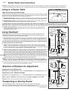
3. Select #11 blue bushing, ( Two #15 retainers ) #21 lead screw,
#22 rapid collar, #23 O-ring, #24 thumb screw, #25 black set
screw, #26 top drive, #27 yellow set screw, #28 allen wrench,
red grease. Using ( fig 9 ) place grease on threads of #21 lead-
screw, Place lead screw down #1 mainshaft and thread into
#19 short nut until one inch of mainshaft extends above head
of #21 lead screw. Alignment of #1mainshaft and #21 screw
hex is required ( fig 10 ).
Tip: # 29 speed wrench can be used to speed threading.
#1
Mainshaft
#7 Brass
Washer
#12 Green
Bushing
#14 Steel 3/16"
Washer
#15 One
Retainer
#13 Hollow
Spring Guide
Flange Up
#29 Speed
Wrench
fig 7
Teeth
Up
© 2000-2005 Router Technologies
All Rights Reserved
Sub-base Plate or Router Table Insert Plate Installation
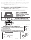
2. See pages 4,5,6, for further instruction, #30 dust cover insert and #31 dust cover, are
table insert only. Drill a 1/2" hole through insert plate at the Router Raizer access point
and press #30 in from top until flush. # 31 sets in #30 and is removed during adjustments
with magnet on back edge of # 29
speed handle. These components
keep dust from entering the
Router Raizer hex drive.
4. Place # 25 set screw into #22 rapid collar. Place rapid collar
onto #1 mainshaft 1/2" from top of mainshaft to top of rapid
collar and tighten. Release plunge lock and slowly raise the router until lead screw
contacts the rapid collar.If the collar moves, reset to 1/2". Place one #15 retainer teeth up
on top of #1mainshaft, using #11 blue bushing as installation tool, push retainer into
contact with collar, repeat with second #15 retainer and push flush with first retainer.
Return #11 blue bushing to box. Place #26 top drive onto #1 mainshaft until it contacts
retainer clip, Thread #27 yellow set screw into #26 top drive using #28 allen wrench and
tighten.
1. Use #46 locating pin to locate the Router Raizer access hole on the original subbase or
router table. For detailed instructions see page 4. Drill original subbase hole to 3/4"
( fig 11 ). For router table installation see 3/4" pocket or 8" X 8" black rubber spacer
pages4,5,6.
3. Periodic inspection and
re-greasing of #21 lead screw
is recommended.
#16 Housing
Bushing
#18 Drive Nut
Washer
#19 Short Drive
Nut
#15 Two
Retainers
#21 Lead Screw
#27 Yellow Set
Screw
#23 O-Ring
#22 Rapid Collar
#4 Two Green
Rollpins
#24 Thumb
Screw
#13Hollow
Spring Guide
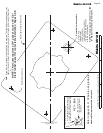
fig 10
Top veiw of #21 lead
screw and #1 main-
shaft through center.
#1 Mainshaft
Note for step 4. On most Makita 3612 routers. #23 O-ring and
#24 thumb screw will not clear the case. Substitute #25 black set
screw and # 28 allen wrench. Install into #22 rapid collar.
If #24 Thumb screw is preferred, Notching of the motor housing
and brush cover will be required.