


Page 26
Makita 3612 Series
Router Raizer Parts Required: ( see page 1) #1, #2, #4, #7, #11, #12, #13, #14, ( three #15 ) #16, #18, #19, #21, #22, #23, #24, #25, #26,
#27, #28, #29, ( #30, #31, #46 for router table installation ).
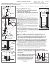
Preparing Motor Housing
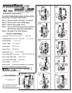
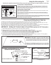
1. Using ( fig 1 ) plunge router down and engage plunge lock.
Remove height knob from height rod.
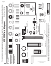
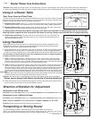
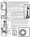
4. Select #1 mainshaft, #16 housing bushing, #18 drive nut
washer, #19 short drive nut. Using ( fig 3 ), drop #16 housing
bushing threads up onto #1 mainshaft. Start #1 mainshaft into
bottom of housing and push up through drille hole. Grasp top
of #1 mainshaft and pull #16 bushing into final position. Drop
#18 washer then #19 nut onto #1 mainshaft, and tighten #19
nut onto #16 bushing using 11/16" wrench. Remove #1 main-
shaft
NOTE: #18 washer must fit on small shoulder #19 nut compare
to inset A ( fig 3 )
Tip: If #19 nut will not tighten insert long flat blade screwdriver
from bottom into post bore to wedge #16 housing bushing
while tightening #19 short nut
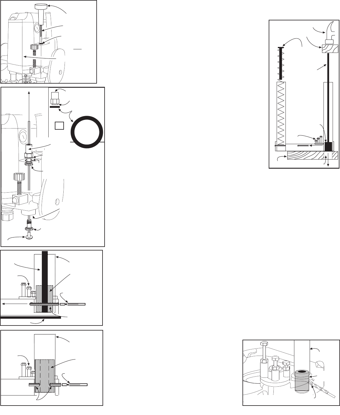
Fig 4
Turret
Stop
Plunge
Post
Fig 6
Turret
Stop
Plunge
Post
Fig 5
2. Stand router upright, grasp both handles, release plunge lock
and lift motor to clear plunge springs. Remove and set aside
plunge springs with the Original steel spring guide in top of non
turret side post.
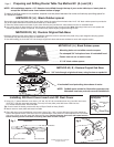
1. Select: hammer, #2 green drive pin. Using ( fig 4 ) remove round subbase.
Line #2 green drive pin up with the height rod roll pin and drive roll pin from base.
Note: this roll pin can drive out hard, and may require re-straightening of #2 drive pin.
Original Steel
Bushing
#4 Rollpin’s
fig 1
Height Rod
Hole Drill to 1/2"
Height Rod
Height Knob
Motor Housing
5. Using ( fig 3 ) clean inside all post bushings. Apply a light film
of STP® motor oil treatment. This lubricants anti-friction properties provides the
smoothest possible plunge action, and helps prevent binding and chattering during use.
fig 2
OriginalSteel
Spring Guide
Hammer
Turret
5/8" Hole
Wood Block
Wood Block
Height Rod
Steel Bushing
3. Select a 1/2" drill bit and drill. Using (fig’s 1 & 3 ) drill the motor
housing height rod hole to 1/2".
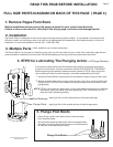
Preparing the Base
2. Prepair a wood block approx. 3/4" X 8" X 4" with a 5/8" hole drilled 1" from one end.
Using ( fig’s 2 & 4 ) stand base upright with height rod bushing centered over 5/8" hole.
Place scrapwood block on top of height rod, drive height rod and bushing down out of
the post. Store height rod pin, height rod and bushing, and height knob.
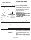
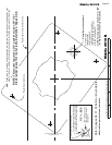
Note: the following step secures the post and #12 green bushing to the base using two
roll pins. Both roll pins are installed from the outside of the base, and cannot extend into
the green bushing bore shown dotted lines ( fig 6 ) If #4 green roll pins extend into bore,
insert a screwdriver into bottom of bushing bore and push pins flush.
#12 Green
Bushing
# 2 Green
Drive Pin
Subbase
Height rod
roll pin
Height rod
# 2 Green
Drive Pin
TOP
TOP
3. Select #12 green nylon bushing. Using ( fig 5 ) turn base upside down with posts on scrap
peice of wood. Drive #12 green bushing into bottom of turret side post until flush with
bottom edge of post. Note: this bushing drives in hard, sanding a slight chamfer on
one end of the bushing aids in installation. The post can be removed from the base
to install this bushing. Once installed drill hole through # 12 green bushing to 21/64"
or ream with 5/16" bit until #1 mainshaft head spins free when placed into bushing.
© 2000-2005 Router Technologies
All Rights Reserved
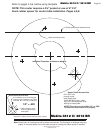
NOTE: Check Off Each Step When Done
1. Cut #1 mainshaft to 10, 1/8" overall length and debur cut end. Set aside to install later.
4. If post was removed for step 3. Replace post, Using ( fig 5 ) line up the post rollpin hole
with the rollpin hole through the base. If post was not removed make sure the rollpin
holes are lined up. The green bushing driven in must be drilled for the roll pins,Using a 13/64"
twist drill, drill straight through original rollpin hole and bushing.
Note: this is easily done with a hand drill, when drilling the bit will center itself on the
inside rollpin hole,
5. Select two #4 green roll pins and #2 green drive pin.
Using ( fig 6 ) place one green roll pin into hole, drive
in until flush with outside of base. Align #2 green
drive pin with roll pin, and drive through original
steel bushing to opposite side. Check and adjust
this roll pin to be flush inside bushing bore. Start
second green roll pin into base, drive in leaving
1/8" exposed. Check bore and adjust if necessary.
Align post and base rollpin holes
Drill completely through using 13/64" bit
#12 Green
Bushing
Plunge Post
Place #16 threads up on
#1 mainshaft then pull #16
into final position
fig 3
#1 mainshaft
#18 Drive Nut
Washer
Small Shoulder
#19 Short Drive Nut
A
Motor Housing
#16 Housing Bushing
Final Position
#18 Drive Nut Washer
#19 Short Drive
Nut
Height Rod Hole Drill to 1/2"
Post
Bushing
Apply Light
Film Of STP®
See other side to finish installation