


OM-206 Page 11
SECTION 3 – INSTALLATION
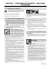
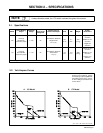
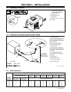
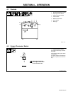
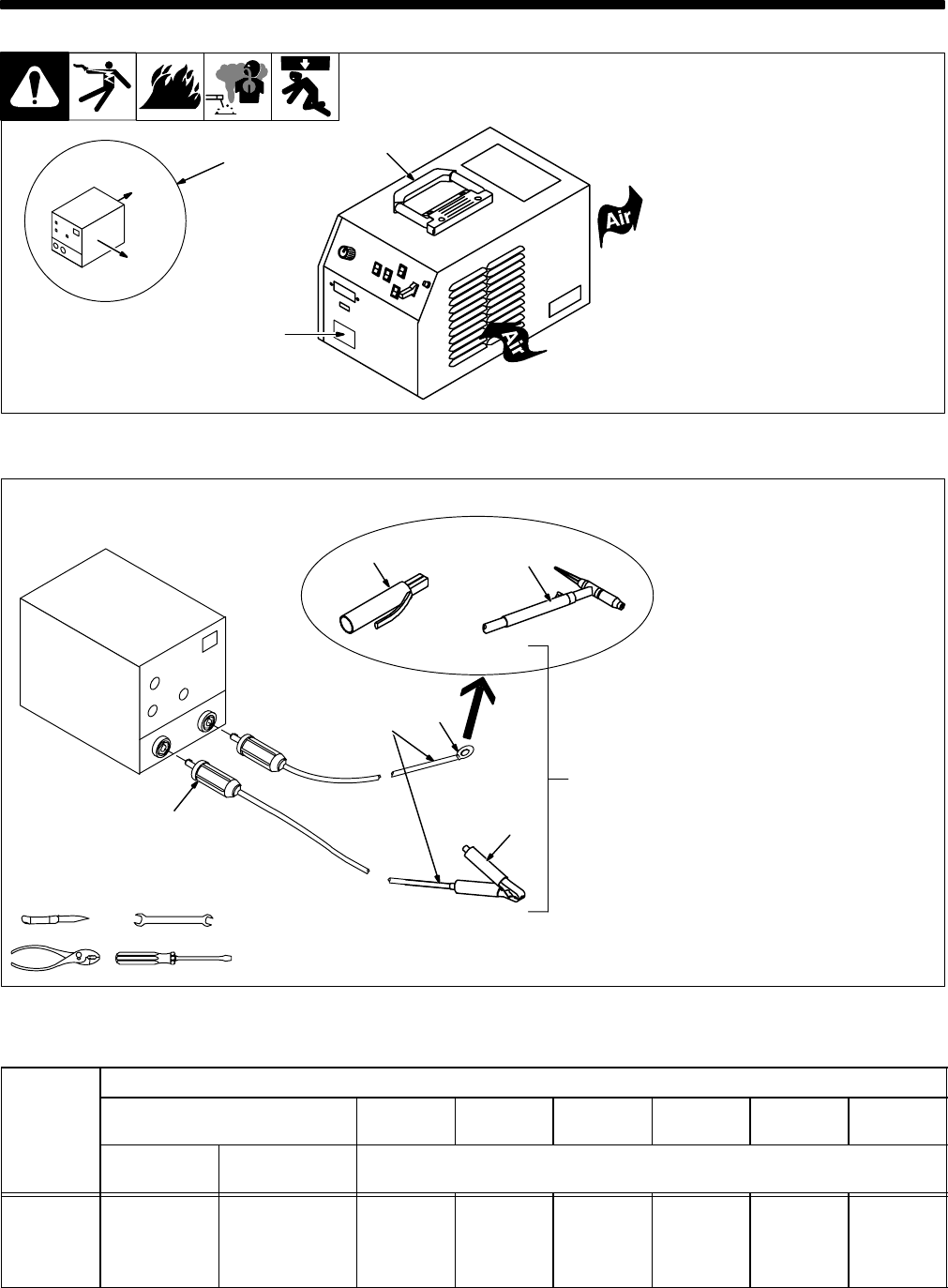
1 10 in (254 mm) Open Space
On Right Side And Rear Of
Unit For Good Airflow
2 Lifting Handle
Use handle to move unit.
3 Rating Label
Locate unit near correct input
power supply.
Right
Rear
1
3-1. Selecting A Location
Ref. SA-145 666-C
2
3
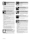
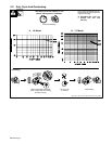
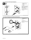
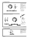
1 Weld Output Cable
Determine total cable length in weld
circuit and maximum welding am-
peres. Use Section 3-3 to select
proper cable size.
Use shortest cables possible.
Do not use damaged cables.
2 Terminal Lug
Use lugs of proper amperage ca-
pacity and hole size for connecting
to work clamp, electrode holder, or
wire feeder.
3 Insulated Electrode Holder
Install according to manufacturer’s
instructions.
4 Work Clamp
Install onto work cable.
5 Dinse-Type Connector
Install onto weld cable.
10 ft (3 m)
Total Cable
Length In Weld
Circuit = 20 ft (6 m)
10 ft (3 m)
For Example,
sb6.2* 5/94 – S-0656
2
5
1
6
Tools Needed:
4
3
OR
3-2. Selecting And Preparing Weld Output Cables
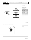
3-3. Weld Cable Size*
Total Cable (Copper) Length In Weld Circuit Not Exceeding
100 ft (30 m) Or Less
150 ft
(45 m)
200 ft
(60 m)
250 ft
(70 m)
300 ft
(90 m)
350 ft
(105 m)
400 ft
(120 m)
Welding
Amperes
10 To 60%
Duty Cycle
60 Thru 100%
Duty Cycle
10 Thru 100% Duty Cycle
100 4 4 4 3 2 1 1/0 1/0
150 3 3 2 1 1/0 2/0 3/0 3/0
200 3 2 1 1/0 2/0 3/0 4/0 4/0
250 2 1 1/0 2/0 3/0 4/0 2-2/0 2-2/0
*Weld cable size (AWG) is based on either a 4 volts or less drop or a current density of at least than 300 circular mils per ampere. S-0007-D