


OM-206 Page 13
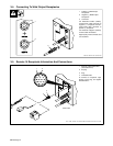
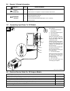
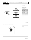
3-6. Remote 14 Socket Information
A +15 volts dc.
B Contact closure to A completes +15 volts dc contactor control circuit.
C Output command reference; 0 to +10 volts dc depending on setting of
Amperage Adjustment control R4.
D Remote control circuit common.
E Input command signal (potentiometer wiper or 0 to +10 volts dc).
K Chassis common
Socket InformationSocket*
REMOTE 14
OUTPUT
(CONTACTOR)
AMPERAGE/
A/V
VOLTAGE
*The remaining sockets are not used.
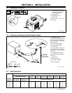
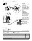
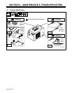
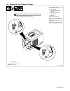
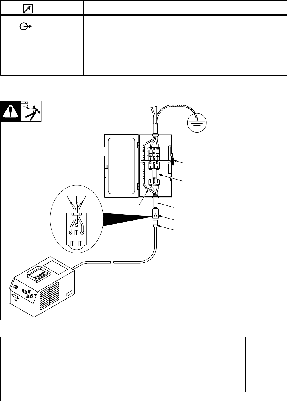
Have only qualified persons make
this installation.
1 Line Disconnect Device Of
Proper Rating
2 230 Volts AC Wall Receptacle
3 Input Conductors
4 Grounding Conductor
Select size and length using Sec-
tion 3-8. Conductor rating must
comply with national, state, and
local electrical codes.
Install and connect input conduc-
tors and grounding conductor in
conduit or equivalent between wall
receptacle and deenergized line
disconnect device.
Connect grounding conductor first,
then line input conductors.
Be sure grounding conductor goes
to an earth ground.
5 Overcurrent Protection
Select type and size using Section
3-8. Install into deenergized line
disconnect device (fused discon-
nect switch shown).
6 Input Power Plug
Turn Off unit Power switch, and
connect plug to receptacle.
ssb2.2* 1/94 – ST-156 250-A
1
3
34
5
6
3
4
2
3-7. Connecting Input Power To 152 Models
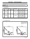
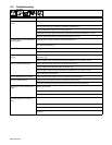
3-8. Electrical Service Guide For 152 Ampere Models
Input Voltage
230
Input Amperes At Rated Output
27.1
Max Recommended Standard Fuse Or Circuit Breaker Rating In Amperes
40
Min Input Conductor Size In AWG/Kcmil
10
Max Recommended Input Conductor Length In Feet (Meters)
167 (51)
Min Grounding Conductor Size In AWG/Kcmil
10
Reference: 1993 National Electrical Code (NEC). S-0092J