


OM-206 Page 15
SECTION 4 – OPERATION
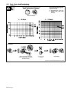
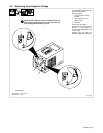
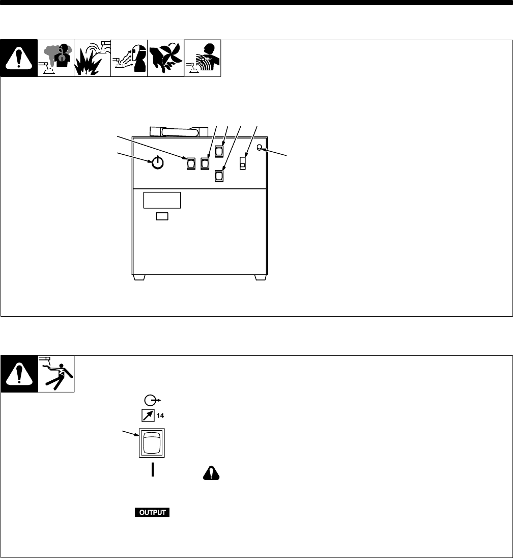
ST-152 127-A
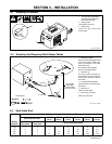
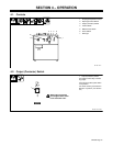
1 Amperage Adjustment Control
2 Amperage Control Switch
3 Output (Contactor) Switch
4 Lift-Arc Switch
5 Weld Process Switch
6 Power Switch
7 Pilot Light
1
2
34 5 6
7
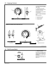
4-1. Controls
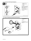
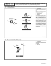
1 Output (Contactor) Switch
Use switch to select way of control-
ling output.
For front panel control, place switch
in On position.
For remote control, place switch in
Remote 14 position (see Section
3-5).
Weld output receptacles
are energized when switch
is On and Power is On.
1
Ref. SC-157 579-A
4-2. Output (Contactor) Switch