


OM-206 Page 14
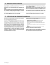
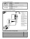
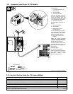
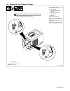
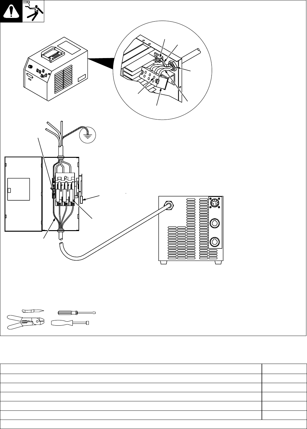
Have only qualified persons make
this installation.
1 Line Disconnect Device Of
Proper Rating
2 Input Conductors
3 Grounding Conductor
Select size and length using Sec-
tion 3-10. Conductor rating must
comply with national, state, and
local electrical codes. Strip 3/8 in
(10 mm) insulation off conductors.
4 Strain Relief Connector
Remove wrapper and insert con-
ductors.
5 Input Terminal Block
6 Line Terminals
7 Welding Power Source
Ground Terminal
Connect grounding conductor to
ground terminal first. Then connect
input conductors to line terminals.
Tighten strain relief connector.
8 Disconnect Device Ground
Terminal
Install and connect grounding
conductor and input conductors in
conduit or equivalent to deener-
gized line disconnect device.
Connect grounding conductor first,
then line input conductors. Be sure
grounding conductor goes to an
earth ground.
Reinstall wrapper.
9 Overcurrent Protection
Select type and size using Section
3-10. Install into deenergized line
disconnect device (fused
disconnect switch shown).
ssb2.4* 1/94 – ST-145 667-B / SA-145 666-C
7
3
4
2
5
1
9
Tools Needed:
5/16 in
6
3
8
3-9. Connecting Input Power To 175 Models
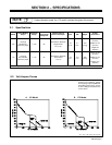
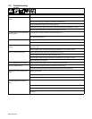
3-10. Electrical Service Guide For 175 Ampere Models
Input Voltage
460
Input Amperes At Rated Output
7.4
Max Recommended Standard Fuse Or Circuit Breaker Rating In Amperes
10
Min Input Conductor Size In AWG/Kcmil
14
Max Recommended Input Conductor Length In Feet (Meters)
443 (135)
Min Grounding Conductor Size In AWG/Kcmil
14
Reference: 1993 National Electrical Code (NEC). S-0092J