


OM-659 Page 3
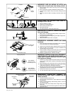
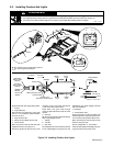
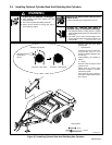
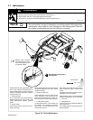
3-2. Installing Fenders And Lights
WARNING
TILTING OF TRAILER can result in personal injury or equipment damage.
• Use adequate blocks or lifting device to support hitch end while pivoting trailer jack into position (see Section 3-1).
• Use trailer jack to obtain desired height and to support tongue weight while installing fenders and lights.
rwarn1.1* 3/93
ST-800 015 / ST-000 297-E
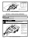
Support trailer with jack. Apply parking brake.
1 Fender
2 Support Bracket
Attach fenders and brackets to frame with
3/8-16 x 1-1/4 in hardware. Tighten hardware
to 30 ft lb (40 N
.
m).
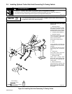
3 Ring Terminal Lead
4 Wiring Harness White Ground Lead
5 Tab Connector
Splice ring terminal lead to white lead with
supplied connector (see Figure 3-3).
Secure ring terminal to side rail using 1/4-20
hardware. If hole is not present, drill a 9/32 in
(7 mm) hole in side rail as shown.
Route brown and green leads through
clamps on right inside of frame and out end of
channel.
6 Sleeving
Slip sleeving over leads. Route leads through
back of right taillight bracket.
7 Taillight
8 Tail Hole
9 Stop Hole
Insert stripped end of brown lead into Tail hole
in rear of right taillight. Insert green lead into
taillight Stop hole. Attach taillight to bracket
with 1/4 in hardware.
10 Sidelight
11 Marker Brown Hole
Route stripped end of either supplied short
lead through hole in right trailer frame chan-
nel. Insert lead into top Marker Brown hole.
Splice remaining end of short lead to brown
lead from wiring harness.
Secure sidelight with 10 - 24 hardware.
Install left side taillight and sidelight using wir-
ing harness brown and yellow leads.
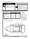
LEFT
RIGHT
To TrailerTo Vehicle
YellowBrown
Lead Lead
Sidelight
Brown Green
LeadLead
Ground
(White)
Taillights
(Brown)
Left Stop/
Signal Lamps
(Yellow)
Right Stop/
Signal Lamps
(Green)
Short Leads
Ground Lead
(Ground To Trailer Frame)
Tab Connector
White (Ground) Lead
Taillights
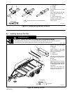
Tools Needed:
7/16, 9/16 in
5/8 in
9/32 in
1
2
3
4
5
6
7
8
9
10
11
Disconnect from vehicle wiring harness
before beginning installation.
Figure 3-2. Installing Fenders And Lights