


. A complete Parts List is available at www.MillerWelds.com
OM-1327 Page 13
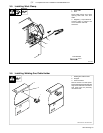
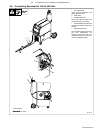
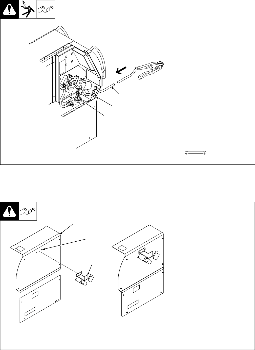
3-5. Installing Work Clamp
1 Work Cable
2 Boot
Route cable through front panel
opening. Slide boot onto work
cable.
3 Negative (−) Output Terminal
Connect cable to terminal and
cover connection with boot.
Close door.
803 540-C
Tools Needed:
3/4 in.
3
2
1
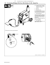
3-6. Installing Welding Gun/Cable Holder
1 Welding Gun/Cable Holder
2 Wrapper
3 Screw Locations
Remove screws from side panel.
Place holder against side panel and
align screw holes. Secure holder to
side panel with the previously
removed screws.
Ref. 803 545-D / Ref. 803 539-C
1
2
3