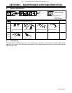
. A complete Parts List is available at www.MillerWelds.com
OM-1327 Page 42
221 044-A / Ref. 803 550-B
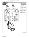
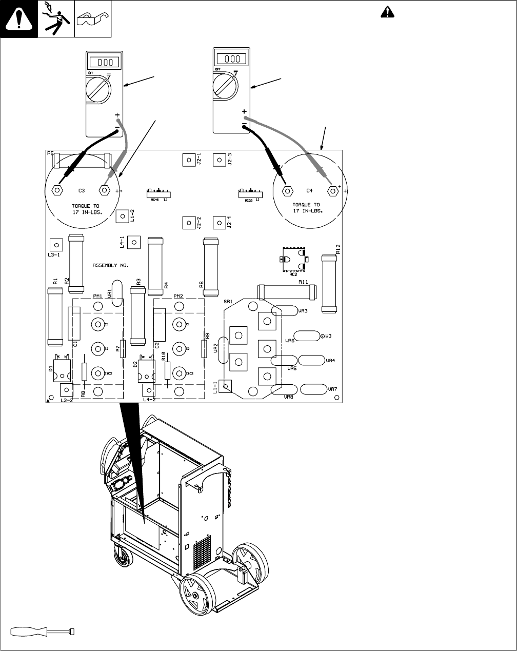
! Significant DC voltage can
remain on capacitors after
unit is Off. Always check ca-
pacitors as shown to be sure
they have discharged before
working on unit.
Turn Off welding power source and
disconnect input power.
Remove case.
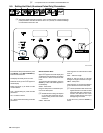
1 Input Capacitor C3 Terminals
2 Input Capacitor C4 Terminals
3 Voltmeter
Check input capacitors as shown.
Measure the dc voltage across the
positive (+) and negative (−)
terminals until voltage drops to near
0 (zero) volts.
Proceed with job inside unit.
Reinstall case when finished.
Tools Needed:
5/16 in.
3
6-3. Measuring Input Capacitor Voltage
3
2
1


