


. A complete Parts List is available at www.MillerWelds.com
OM-1327 Page 21
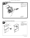
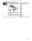
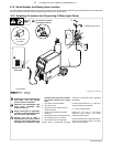
3-15. Serial Number And Rating Label Location
The serial number and rating information for this product is located on back. Use rating label to determine input power requirements and/or rated output.
For future reference, write serial number in space provided on back cover of this manual.
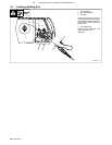
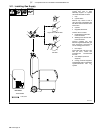
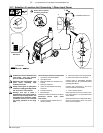
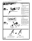
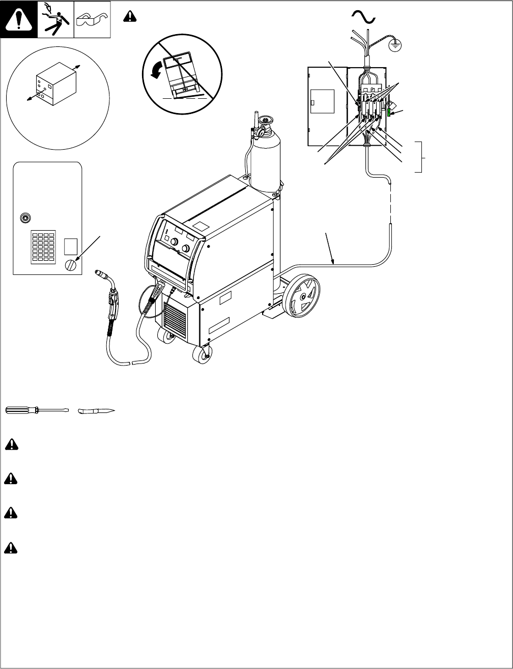
3-16. Selecting A Location And Connecting 3-Phase Input Power
Ref. 803 543-E / 803 766-A
! Installation must meet all National and
Local Codes - have only qualified
persons make this installation.
! Disconnect and lockout/tagout input
power before connecting input
conductors from unit.
! Always connect green or green/yellow
conductor to supply grounding terminal
first, and never to a line terminal.
! Warning: This unit is either a
200/230/460 ac input voltage model or
460/575 ac input voltage model. See
rating label on unit and check voltage
available at site to be sure it matches
the voltage specified on the rating
label.
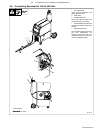
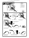
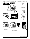
1 Input Power Cord Strain Relief
2 Input Power Cord
3 Disconnect Device (switch shown in
the OFF position)
4 Green Or Green/Yellow Grounding
Conductor
5 Disconnect Device Grounding Terminal
6 Input Conductors (L1, L2 And L3)
7 Disconnect Device Line Terminals
Connect green or green/yellow grounding
conductor to disconnect device grounding
terminal first.
Connect input conductors L1, L2, and L3 to
disconnect device line terminals.
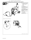
8 Over-Current Protection
Select type and size of over-current
protection using Section 3-13 (fused
disconnect switch shown).
Close and secure door on disconnect device.
Remove lockout/tagout device, and place
switch in the On position.
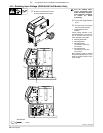
Tools Needed:
2
1
Rear Panel
18 in. (457 mm)
for airflow
! Do not move or operate
unit where it could tip.
= GND/PE Earth Ground
3
3
4
5
7
6
8
L1
L2
L3