


OM-477 Page 14
SECTION 4 – INSTALLATION
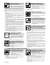
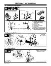
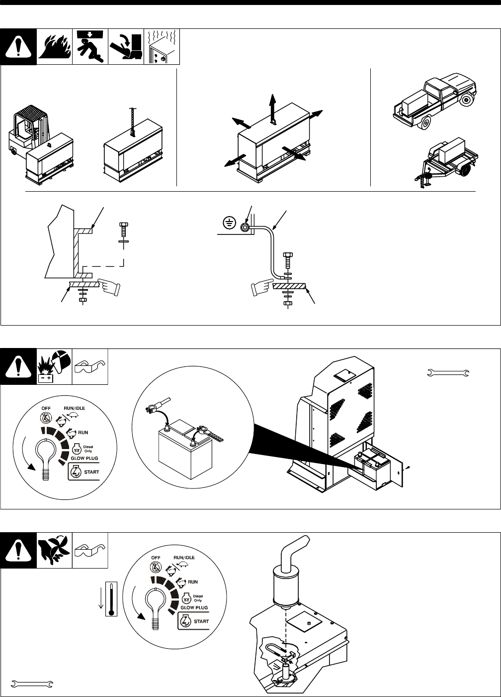
4-1. Installing Welding Generator
install1 12/99 – Ref. ST-800 652 / Ref. ST-800 477-A / ST-158 936-A / S-0854
1
2
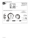
Electrically bond generator frame to
vehicle frame by metal-to-metal
contact.
GND/PE
3
4
Y Always ground generator frame to ve-
hicle frame to prevent electric shock
and static electricity hazards.
1 Generator Base
2 Metal Vehicle Frame
3 Equipment Grounding Terminal
4 Grounding Cable
Use #10 AWG or larger insulated copper wire.
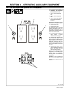
Y If unit does not have GFCI receptacles,
use GFCI-protected extension cord.
2
OR
18 in
(460 mm)
18 in
(460 mm)
18 in
(460 mm)
18 in
(460 mm)
18 in
(460 mm)
OR
Movement Airflow Clearance Location
Grounding
OR
Y Do Not Lift Unit From End
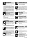
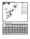
4-2. Connecting The Battery
Ref. ST-138 751-B / Ref. ST-191 898 / Ref. S-0756-C
Tools Needed:
1/2 in
–
+
Y Connect
Negative (–)
Cable Last
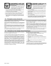
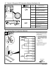
4-3. Installing Muffler
Tools Needed:
muff1 4/96 – ST-154 088-B / Ref. ST-191 898
1/2 in
Y Stop engine and let cool.
Y Do not blow exhaust toward
air cleaner or air intake.