


OM-477 Page 29
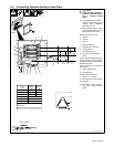
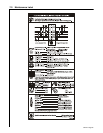
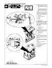
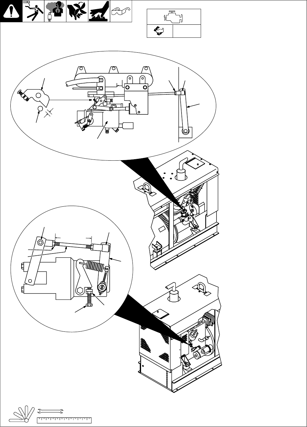
7-8. Adjusting Engine Weld/Power Speed
Ref. ST-801 179 / Ref. ST-800 159-C / Ref. ST-800 161
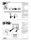
. Governor sensitivity may re-
quire adjustment if engine
speed is adjusted (see Section
7-10).
If linkage binds, loosen socket
nuts and turn sockets until link-
age works smoothly. Tighten
nuts.
After tuning engine, check engine
no load speed with a tachometer
(see table for no load speeds). If
necessary, adjust speed as follows:
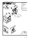
1 Socket Nut
2 Governor Linkage Rod
3 Lock Nut
4 Socket
5 Governor Arm
Rod length should be 3-1/4 in (83
mm) between lock nuts. To adjust,
remove socket from arm and loos-
en lock nut. Turn socket to adjust
length. Tighten nut and reattach
socket to arm.
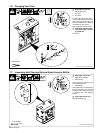
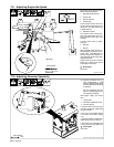
6 Carburetor
7 Throttle Stop Plate
8 Throttle Stop
Clearance between plate and stop
should be 1/16 in (1.6 mm). To ad-
just clearance, proceed as follows:
9 Linkage Pivot Arm
10 Linkage Socket
11 Lock Nut
Remove socket at arm and loosen
lock nut. Turn socket to adjust
clearance. Reattach socket and
tighten nut.
Start engine and run until warm.
Turn Engine Control switch to Run
position.
12 Governor Speed Screw
13 Lock Nut
Loosen nut. Turn screw until engine
runs at weld/power speed.
Y Stop engine.
Close door.
Tools Needed:
3/8, 7/16 in
1850 rpm
(max)
2
3
4
5
6
7
8
9
1011
12
13
3-1/4 in
(83 mm)
1/16 in
(1.6 mm)
1