


OM-477 Page 16
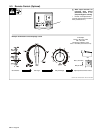
ST-800 162-A
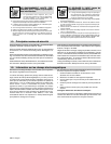
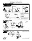
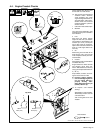
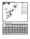
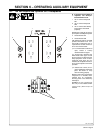
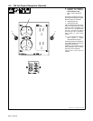
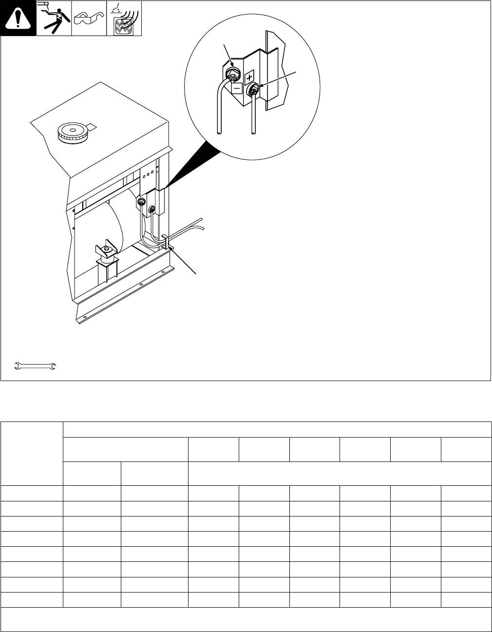
Open left side door.
1 Bracket
Route cables through bracket.
2 Positive (+) Weld Output
Terminal
3 Negative (–) Weld Output Ter-
minal
For Stick welding Direct Current
Electrode Positive (DCEP), con-
nect work cable to (–) terminal and
electrode holder cable to (+)
terminal.
For Direct Current Electrode Nega-
tive (DCEN), reverse cable
connections.
If equipped with optional polarity
switch, connect electrode holder
cable to Electrode (–) terminal and
work cable to Work (+) terminal.
For MIG and FCAW welding with
CV option, connect work cable to
(–) terminal and wire feeder cable to
(+) terminal
Close door.
Tools Needed:
3
Left Side
2
1
3/4 in
4-5. Connecting To Weld Output Terminals
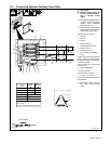
4-6. Selecting Weld Cable Sizes
Total Cable (Copper) Length In Weld Circuit Not Exceeding
Welding
Amperes
100 ft (30 m) Or Less
150 ft
(45 m)
200 ft
(60 m)
250 ft
(70 m)
300 ft
(90 m)
350 ft
(105 m)
400 ft
(120 m)
Amperes
10 – 60%
Duty Cycle
60 – 100% Duty
Cycle
10 – 100% Duty Cycle
100 4 4 4 3 2 1 1/0 1/0
150 3 3 2 1 1/0 2/0 3/0 3/0
200 3 2 1 1/0 2/0 3/0 4/0 4/0
250 2 1 1/0 2/0 3/0 4/0 2-2/0 2-2/0
300 1 1/0 2/0 3/0 4/0 2-2/0 2-3/0 2-3/0
350 1/0 2/0 3/0 4/0 2-2/0 2-3/0 2-3/0 2-4/0
400 1/0 2/0 3/0 4/0 2-2/0 2-3/0 2-4/0 2-4/0
500 2/0 3/0 4/0 2-2/0 2-3/0 2-4/0 3-3/0 3-3/0
*Weld cable size (AWG) is based on either a 4 volts or less drop or a current density of at least 300 circular mils per ampere. Contact your
distributor for the mm
2
equivalent weld cable sizes. S-0007-E