


OM-4433 Page 19
SECTION 5 − INSTALLATION
install3 2007−04 − Ref. 800 652 / Ref. 800 477-A / 803 274 / 804 712
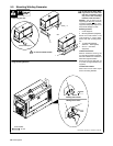
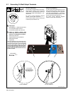
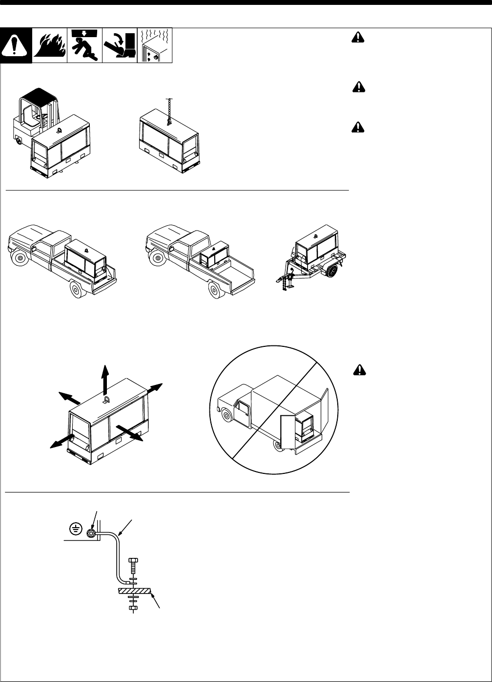
! Always securely fasten weld-
ing generator onto transport
vehicle or trailer and comply
with all DOT and other applica-
ble codes.
! Always ground generator
frame to vehicle frame to pre-
vent electric shock and static
electricity hazards.
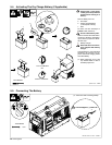
! If unit does not have GFCI re-
ceptacles, use GFCI-protected
extension cord.
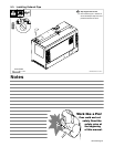
NOTICE − Do not install unit where
air flow is restricted or engine may
overheat.
. See Section 4-2 for lifting eye
rating.
. See Section 5-2 for mounting
information.
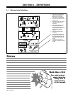
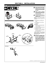
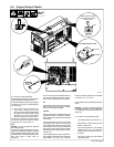
Grounding:
1 Equipment Grounding Terminal
(On Front Panel)
2 Grounding Cable (Not Supplied)
3 Metal Vehicle Frame
. Electrically bond generator
frame to vehicle frame by met-
al-to-metal contact.
Connect cable from equipment
ground terminal to metal vehicle
frame. Use #10 AWG or larger insu-
lated copper wire.
! Bed liners, shipping skids,
and some running gears insu-
late the welding generator
from the vehicle frame. Al-
ways connect a ground wire
from the generator equipment
grounding terminal to bare
metal on the vehicle frame as
shown.
GND/PE
1
2
3
18 in
(460 mm)
18 in
(460 mm)
18 in
(460 mm)
18 in
(460 mm)
18 in
(460 mm)
Movement
5
-1. Installing Welding Generator
OR
Grounding
OR
Location/Airflow Clearance
OR