


OM-4433 Page 33
SECTION 7 − OPERATING AUXILIARY EQUIPMENT
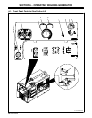
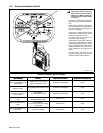
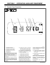
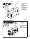
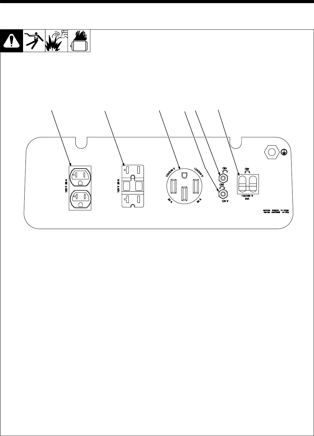
7-1. Generator Power Receptacles
217 357-A
1 120 V 20 A AC (shown)
Receptacle RC5 and/or GFCI1
2 120 V 20 A AC GFCI (shown)
Receptacle RC6 and/or GFCI2
3 240 V 50 A AC
Receptacle RC11
RC5 / 6 and GFCI1 / 2 supply 60 Hz single-
phase power at weld/power speed. Recep-
tacle configuration varies depending on
machine model and serial number.
Maximum output from these receptacles is
2.4 kVA/kW.
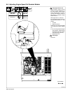
If a ground fault is detected, GFCI Reset
button pops out and receptacle does not
work. Check for faulty equipment plugged
in receptacle. Press button to reset GFCI
receptacle.
. At least once a month, run engine at
weld/power speed and press test but-
ton to verify GFCI is working properly.
RC11 supplies 60 Hz single-phase power
at weld/power speed. Maximum output
from RC11 is 10 kVA/kW.
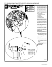
4 Supplementary Protector CB4
5 Supplementary Protector CB6
6 Supplementary Protector CB5
CB4 protects RC6 / GFCI2 and CB6 pro-
tects RC5 / GFCI1 from overload. If a sup-
plementary protector opens, the receptacle
does not work. Press button to reset.
Supplementary protector CB5 protects re-
ceptacles and the generator winding from
overload. If CB5 opens, the receptacles do
not work. Place CB5 switch in On position
to reset circuit breaker.
. If a supplementary protector continues
to open, contact Factory Authorized
Service Agent.
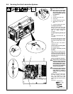
. Generator power decreases as weld
output increases.
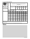
Combined output of all receptacles is limit-
ed to the 10 kVA/kw rating of the generator.
EXAMPLE: If 15 A is drawn from each 120
V receptacle , only 26 A is available at the
240 V receptacle:
2 x (120 V x 15 A) + (240 V x 26 A) =
10.0 kVA/kW
1 2
3456