


OM-496 Page 36
Return To Table Of Contents
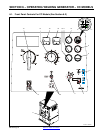
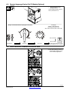
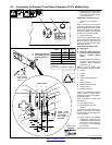
7-3. Process/Contactor Switch On CC/CV Models
1 Process/Contactor Switch
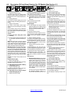
Y Weld output terminals are ener-
gized when Process/Contactor
switch is in an Electrode Hot
position and the engine is run-
ning.
Y DC voltage is still present at the
weld terminals when Process/
Contactor switch is in the
Remote − Stick position and the
engine is running.
Use switch to select weld process and
weld output on/off control (see table be-
low and Section 7-4).
Place switch in Remote positions to
turn weld output on and off with a de-
vice connected to the remote 14 recep-
tacle.
Place switch in Electrode Hot positions
for weld output to be on whenever the
engine is running.
Use Stick position for air carbon arc
(CAC-A) cutting and gouging.
When switch is in a Stick position, the
arc drive (dig) circuit provides addition-
al amperage during low voltage (short
arc length conditions) to prevent “stick-
ing” electrodes.
The arc drive (dig) circuit is disabled
when switch is in MIG or TIG positions.
. Place switch in Electrode Hot -
Stick position when using optional
three-phase generator (see Sec-
tion 8-2).
. The engine auto idle option does
not work in the Remote-TIG mode.
1
Process/Contactor Switch Settings
Switch Setting
Process
Output On/Off Control
Engine Auto Idle (Optional)
Switch Setting
Process
Output On/Off Control
Engine Auto Idle (Optional)
Remote − TIG
GTAW With HF Unit, Pulsing
Device, Or Remote Control
At Remote 14 Receptacle Not Active
Remote − Stick Stick (SMAW) With Remote On/Off At Remote 14 Receptacle Active
Remote − MIG MIG (GMAW) At Remote 14 Receptacle Active
Electrode Hot − MIG MIG (GMAW) Electrode Hot Active
Electrode Hot − Stick
Stick (SMAW),
Air Carbon Arc (CAC-A) Cutting
And Gouging
Electrode Hot Active
Electrode Hot − Scratch
Start TIG
Scratch Start TIG (GTAW) Electrode Hot Active