


OM-4421 Page 23
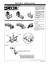
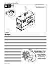
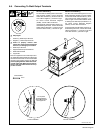
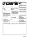
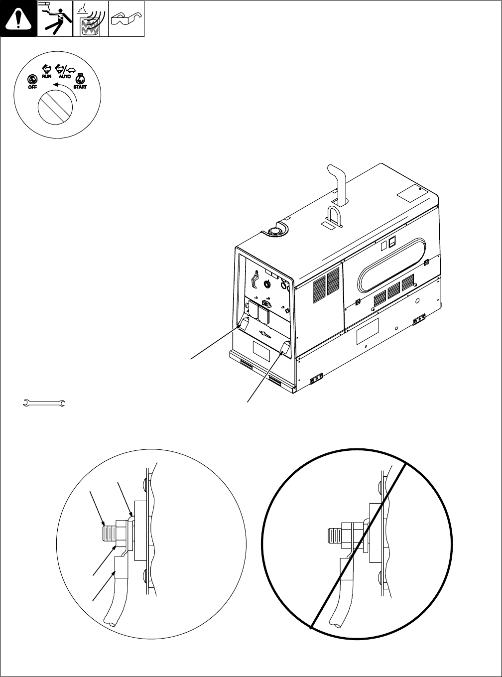
5-8. Connecting To Weld Output Terminals
803 602 / 803 778-A
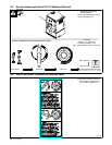
Tools Needed:
2
3/4 in
1
MIG and FCAW Welding
For MIG and FCAW welding Direct Current
Electrode Positive (DCEP) on CC/CV models,
connect wire feeder cable to Positive (+) termi-
nal on left and work cable to Negative (−) ter-
minal on right. Use Process/Contactor switch
to select type of weld output (see Section 7-3).
For Direct Current Electrode Negative
(DCEN), reverse cable connections.
If equipped with optional Polarity switch or op-
tional Polarity/AC switch, connect wire feeder
cable to Electrode (+) terminal on left and
work cable to Work (−) terminal on right.
6
4
5
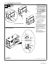
Do not place
anything between
Correct Installation
Incorrect Installation
3
weld cable terminal
and copper bar.
Y Stop engine.
1 Positive (+) Weld Output Terminal
2 Negative (−) Weld Output Terminal
Y Failure to properly connect weld
cables may cause excessive heat and
start a fire, or damage your machine.
3 Weld Output Terminal
4 Supplied Weld Output Terminal Nut
5 Weld Cable Terminal
6 Copper Bar
Remove supplied nut from weld output termi-
nal. Slide weld cable terminal onto weld output
terminal and secure with nut so that weld cable
terminal is tight against copper bar. Do not
place anything between weld cable termi-
nal and copper bar. Make sure that the sur-
faces of the weld cable terminal and cop-
per bar are clean.
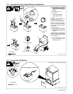
Stick and TIG Welding
For Stick and TIG welding Direct Current Elec-
trode Positive (DCEP), connect electrode
holder cable to Positive (+) terminal on left and
work cable to Negative (−) terminal on right.
For Direct Current Electrode Negative
(DCEN), reverse cable connections.
If equipped with optional Polarity switch or op-
tional Polarity/AC switch, connect electrode
holder cable to Electrode (+) terminal on left
and work cable to Work (−) terminal on right.