


OM-4421 Page 35
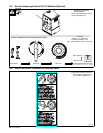
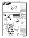
8-2. Connecting To Optional Three-Phase Generator (CC/CV Models Only)
Ref. 197 399 / 802 332-E / 803 655
. Place Process/Contactor switch
in Weld Terminals Always On -
Stick position when using three-
phase generator (see Section
7-3).
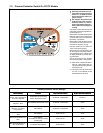
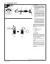
Single-Phase Generator Power
1 120/240 V 50 A Receptacle
RC5
RC5 is connected to the optional
three-phase generator and supplies
60 Hz single-phase power at weld/
power speed. Maximum output from
RC5 is 12 kVA/kW. Power available
at RC5 is reduced when welding.
2 Supplementary Protector CB7
Supplementary Protector CB7 pro-
tects single-phase receptacle RC5
and the load wires from overload. If
CB7 opens, all generator output
stops and the receptacle does not
work.
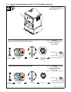
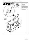
Three-Phase Generator Power
Y Stop engine.
Y Power and weld outputs are
live at the same time. Discon-
nect or insulate unused
cables.
. Have qualified person install ac-
cording to circuit diagram and
Generator Power Guidelines
(see Section 12).
Remove generator power panel
mounting screws. Tilt panel forward.
3 Lead 93
4 Lead 92
5 Lead 91
6 Lead 42 (Circuit Grounding
Lead)
7 Lead 90 (Neutral)
8 Isolated Neutral Terminal
9 Jumper Lead 42
10 Grounding Terminal
Jumper 42 is connected to lead 90 at
factory. Jumper 42 may be discon-
nected from neutral to meet applica-
ble electrical codes.
Lead 42 connects to front panel
Ground stud.
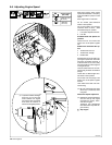
11 User-Supplied Leads
12 Supplementary Protector CB7
User Terminals
Connect user-supplied leads to ter-
minals on CB7 and to the isolated
neutral terminal and grounding termi-
nal as necessary.
. Supplementary protector CB7
protects single-phase receptacle
RC5 and the load wires from
overload. If CB7 opens, all gener-
ator output stops and the recep-
tacle does not work.
Reinstall generator power panel.
Tools Needed:
Volts
Amps
KVA/KW
Single
120/240
50
12
Three
240
36
15
60 HzFrequency
Engine Speed 1850 RPM
AC
Phase
1
Phase
3
Output
Lead 42 connects to GROUND stud on
front of unit.
Jumper 42 is connected to 90 at factory.
12
91 92 93
240V
120V
120V
240V
240V
1-Phase
3-Phase
3
4
5
6
7
8
9
10
11
12
Rear Of Panel
Three-Phase Power Connection
2
Single-Phase Power Connection
92
90
91
93
Y Close panel opening
if no connections are
made to generator.
Y Close panel
opening if no
connections
are made to
generator.
240V
Remove plug
before inserting
leads. Reinstall
bushing.