


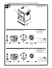

OM-4421 Page 31
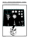
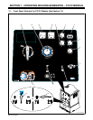
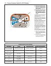
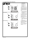
7-2. Description Of Front Panel Controls For CC/CV Models (See Section 7-1)
Engine Starting Controls
1 Starting Aid Switch
Use switch to energize starting aid for cold
weather starting (see starting instructions fol-
lowing).
2 Engine Control Switch
Use switch to start engine, select engine
speed ( if unit has auto idle option), and stop
engine.
In Run position, engine runs at weld/power
speed. In Auto position (optional), engine
runs at idle speed at no load and weld speed
with load applied.
To Start:
Y Do not use ether. Using ether voids
warranty.
. If engine does not start, let engine come
to a complete stop before attempting re-
start.
Above 325 F (05 C): turn Engine Control
switch to Start. Release Engine Control
switch when engine starts.
Below 325 F (05 C): push Starting Aid switch
up for 60 seconds. While still holding Starting
Aid switch, turn Engine Control switch to
Start. Release Engine Control switch and
Starting Aid switch when engine starts.
To Stop: turn Engine Control switch to Off
position.
Engine Gauges And Meters
3 Engine Hour Meter
Use hour meter to monitor engine run time to
help schedule maintenance.
4 Fuel Gauge
Use gauge to check fuel level.
To check fuel level when engine is not run-
ning, turn Engine Control switch to Run posi-
tion
5 Battery Voltmeter (Optional)
Use gauge to check battery voltage and moni-
tor the engine charging system. The meter
should read about 14 volts dc when the en-
gine is running, and about 12 volts dc when
the engine is stopped.
6 Engine Coolant Temperature Gauge
(Optional)
Normal temperature is 180 - 203° F (82 - 95°
C). Engine stops if temperature exceeds 220°
F (104° C).
7 Engine Oil Pressure Gauge (Optional)
Normal pressure is 30 − 60 psi (207 − 414
kPa). Engine stops if pressure is below 10 psi
(69 kPa).
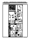
Weld Controls
8 Process/Contactor Switch
See Section 7-3 for Process/Contactor
switch information.
9 Ampere Range Switch
Y Do not switch under load.
Use switch to select weld amperage range.
Use the lowest four ranges for Stick and TIG
welding. Read the upper set of numbers at
each range for Stick welding and the lower set
at each range for TIG welding.
Use the highest range for MIG welding and for
cutting and gouging (CAC-A).
For most welding applications, use lowest
amperage range possible to help prevent arc
outages.
10 Voltage/Amperage Adjust Control
With Process/Contactor switch in any Stick or
TIG setting, use control to adjust amperage
within range selected by Ampere Range
switch. With Process/Contactor switch in any
MIG position, use control to adjust voltage.
With Voltage/Amperage Adjust Switch in Re-
mote position, control limits the remote am-
perage in TIG mode, but has no effect in Stick
and MIG modes.
Weld output would be about 218 A DC with
controls set as shown (50% of 115 to 320 A).
. The numbers around the control are for
reference only and do not represent an
actual percentage value.
11 Voltage/Amperage Adjust Switch And
Remote 14 Receptacle
Use switch to select front panel or remote
voltage/amperage control. For remote con-
trol, place switch in Remote position and con-
nect remote control to Remote 14 receptacle
RC14 (see Sections 5-11 and 7-4).
12 Polarity Switch (Optional)
Y Do not switch under load.
Use Polarity switch to change weld output.
Select either DC Electrode Positive (DCEP)
or DC Electrode Negative (DCEN).
13 Polarity/AC Switch (Optional)
Y Electric shock can kill.
Y Do not use AC output in damp areas,
if movement is confined, or if there is
a danger of falling.
Y Use AC output ONLY if required for the
welding process. If AC output is re-
quired, use remote output control if
present on unit.
Y Do not switch under load.
Use Polarity/AC switch to select AC or DC
weld output and DC weld output polarity. For
Direct Current Electrode Negative (DCEN),
turn switch to − (Negative) position. For Direct
Current Electrode Positive (DCEP), turn
switch to + (Positive) position. For weld pro-
cesses that require alternating current (AC),
use AC position.
Weld Meters
14 AC/DC Voltmeter (Optional)
Voltmeter displays voltage at the weld output
terminals, but not necessarily the welding arc
due to resistance of cable and connections.
15 AC/DC Ammeter (Optional)
Ammeter displays amperage output of the
unit.