


OM-4421 Page 42
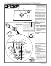
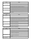
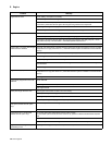
9-6. Adjusting Engine Speed
803 606-C
After tuning engine, check engine
speed with tachometer or frequency
meter. See table for proper no load
speed.
Start engine and run until warm.
On CC models, place Stick/TIG
switch in Stick position.
On CC/CV models, turn Process/
Contactor switch to Stick − Weld
Terminals Always On position.
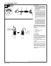
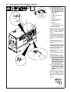
1 Low Speed Adjustment Screw
2 Lock Nut
Standard Model Idle Speed Ad-
justment
Loosen lock nut. Turn screw until
engine runs at idle speed. Tighten
nut.
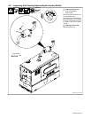
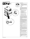
Models With Automatic Idle Op-
tion
3 Throttle Rod Lock Nut
4 Throttle Rod / Plunger
5 Rubber Boot
Adjustment screw is not used to ad-
just engine speed when automatic
idle option is installed. However, it
must be at least 1/8 in (3 mm) away
from the throttle arm when engine is
running at idle rpm.
Unhook rubber boot from the sole-
noid housing but leave connected to
plunger.
Loosen lock nut. Place Engine Con-
trol Switch in Auto position.
Turn throttle rod and plunger until
engine runs at idle speed. Tighten
lock nut.
Hook rubber boot back onto sole-
noid housing.
. Be sure solenoid plunger pulls
all the way in (“bottoms”) when
energized.
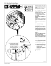
Weld/Power Speed Adjustment
. Weld/power speed adjustment
must be done by the engine
manufacturer’s factory autho-
rized service agent.
Tampering with adjustments
other than shown may affect en-
gine warranty.
Y Stop engine.
1850 rpm max
(61.6 Hz)
1250 rpm
(41.6 Hz)
Engine Speed
(No Load)
2
1
3
4
. To prevent solenoid damage,
be sure a 1/8 in (3 mm) gap
exists between the engine
low speed screw and throttle
lever when the solenoid is
held in the energized position.
5