


OM-498 Page 16
Return To Table Of Contents
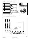
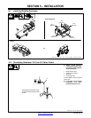
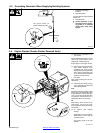
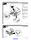
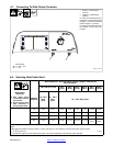
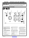
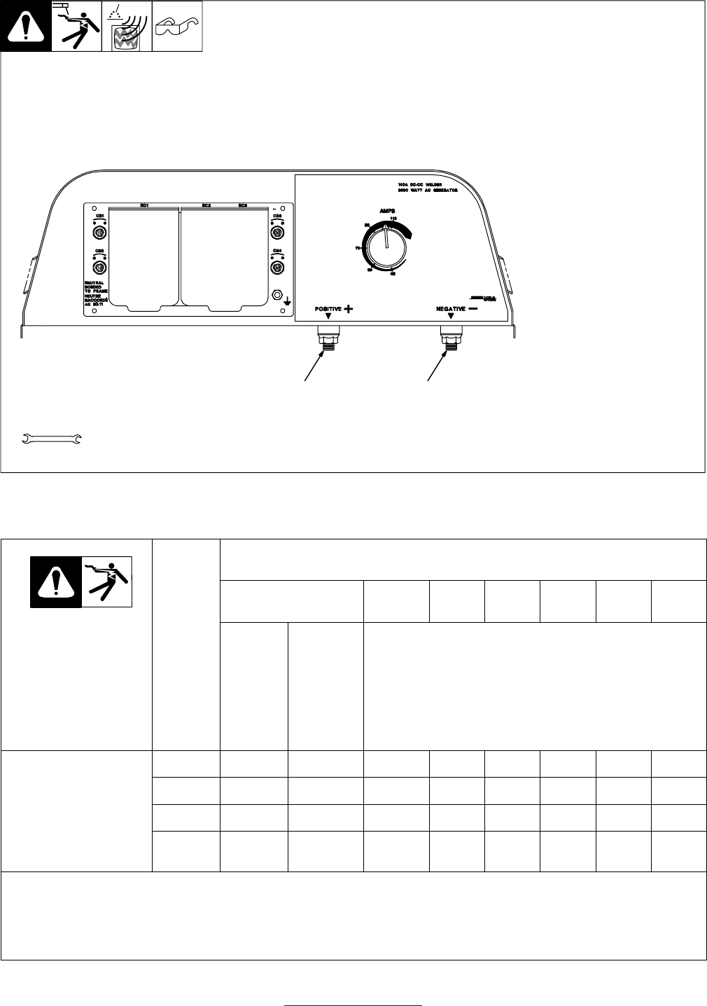
5-7. Connecting To Weld Output Terminals
196 921 / 495 179
1 Positive (+) Weld Output
Terminal
2 Negative (−) Weld Output
Terminal
For Direct Current Electrode Posi
-
tive (DCEP), connect work cable to
Negative (−) terminal and electrode
holder to Positive (+) terminal.
For Direct Current Electrode nega
-
tive (DCEN), reverse cable con
-
nections.
Tools Needed:
3/4 in
12
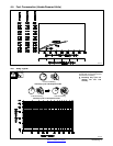
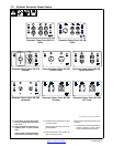
5-8. Selecting Weld Cable Sizes*
Weld Cable Size** and Total Cable (Copper) Length in Weld Circuit
Not Exceeding***
100 ft (30 m) or Less
150 ft
(45 m)
200 ft
(60 m)
250 ft
(70 m)
300 ft
(90 m)
350 ft
(105 m)
400 ft
(120 m)
Weld Output
Terminals
Y Stop engine before
connecting to weld out-
put terminals.
Y Do not use worn, dam-
aged, undersized, or
poorly spliced cables.
Welding
Amperes
10 − 60%
Duty
Cycle
60 − 100%
Duty
Cycle
10 − 100% Duty Cycle
100 4 (20) 4 (20) 4 (20) 3 (30) 2 (35) 1 (50) 1/0 (60) 1/0 (60)
150 3 (30) 3 (30) 2 (35) 1 (50) 1/0 (60) 2/0 (70) 3/0 (95) 3/0 (95)
200 3 (30) 2 (35) 1 (50) 1/0 (60) 2/0 (70) 3/0 (95) 4/0 (120) 4/0 (120)
250 2 (35) 1 (50) 1/0 (60) 2/0 (70) 3/0 (95) 4/0 (120)
2 ea. 2/0
(2x70)
2 ea. 2/0
(2x70)
* This chart is a general guideline and may not suit all applications. If cable overheating occurs (normally you can smell it), use next size larger
cable.
**Weld cable size (AWG) is based on either a 4 volts or less drop or a current density of at least 300 circular mils per ampere.
( ) = mm
2
for metric use S-0007-E
***For distances longer than those shown in this guide, call a factory applications representative at 920-735-4505.