


OM-498 Page 20
Return To Table Of Contents
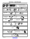
SECTION 7 − OPERATING AUXILIARY EQUIPMENT
The welding generator provides power while welding and with the Current control
in any position. However, under these conditions equipment connected to the
welding generator may be subject to larger than normal voltage fluctuations. It is
recommended that only lamps be powered under these conditions.
NOTE
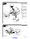
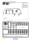
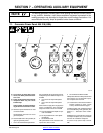
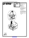
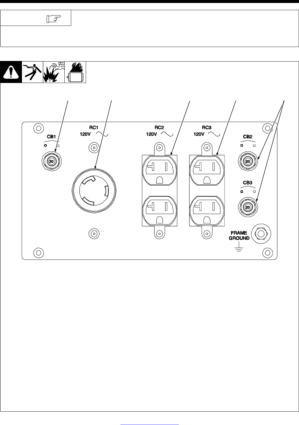
7-1. Generator Power Panel 495 218 (USA)
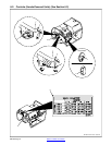
Y If unit does not have GFCI recep-
tacles, use GFCI-protected exten-
sion cord.
Y Power is still present at the 240 volt
receptacle when only one circuit
breaker trips.
Unplug power cord before attempt-
ing to service accessories or tools.
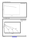
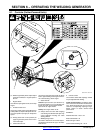
. Generator power decreases as weld
current increases.
Set Amperage control at max. for full
generator power.
. Place throttle lever in Run position (far
right) for generator power.
1 120 V AC Twistlock Receptacle RC1
RC1 supplies 60 Hz single-phase power at
weld/power speed. Maximum output is 3.5
kVA/kW.
2 120 V 20 A AC Duplex Receptacle
RC2
3 120 V 20 A AC Duplex Receptacle
RC3
RC2 and RC3 supply 60 Hz single-phase
power at weld/power speed. Maximum
output from RC2 or RC3 is 2.4 kVA/kW.
. Each receptacle of the duplex can pro-
vide 15A/1800W.
. Do not parallel the two 120V duplex
receptacles.
4 Circuit Breaker CB1
CB1 protects RC1 from overload. If CB1
opens, RC1 does not work.
5 Circuit Breakers CB2 And CB3
CB2 protects RC2 and CB3 protects RC3
from overload. If a circuit breaker opens,
the receptacle does not work.
. Press button to reset circuit breaker. If
breaker continues to open, contact
Factory Authorized Service Agent.
Combined output of all receptacles limited
to 3.5 kVA/kW rating of the generator (See
Section 11 − Generator Power Guide-
lines).
EXAMPLE: If 10 A is drawn from each 120
volt duplex receptacle, only 9 A is available
from the 120 V twistlock receptacle.
2 x (120 V x 10 A) + (240 V x 9 A) = 3.5 kVA/
KW.
495 218
1234 5