


OM-498 Page 17
Return To Table Of Contents
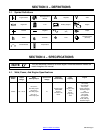
SECTION 6 − OPERATING THE WELDING GENERATOR
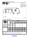
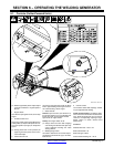
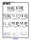
6-1. Controls (Kohler-Powered Units)
802 512-A / 495 179
5
2
60 Hz
3
4
. Weld and generator power output stops if
generator overheats or engine speed is
too low.
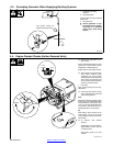
1 Engine Switch
Use switch to open ignition circuit, and to stop
engine.
2 Throttle Control Lever
Use lever to select engine speed. Move lever
to idle position (far left) for idle speed. Move le-
ver to Run position (far right) for weld/power
speed.
. Always place lever in Run position (far
right) for generator power and for maxi-
mum weld output.
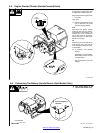
3 Choke Control Lever
Use lever to change engine air/fuel mix. Move
lever to right if starting a cold engine. Move le-
ver to left if starting a warm engine.
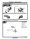
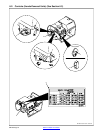
4 Starter Handle
To Start: open fuel valve (see Section 5-4),
turn engine switch to On, move throttle lever
to Idle, set choke, and pull starter handle.
Open choke as engine warms.
To Stop: turn engine switch to Off.
. Always close fuel valve after stopping
unit. Moving unit with fuel valve open may
cause carburetor flooding and make
starting difficult.
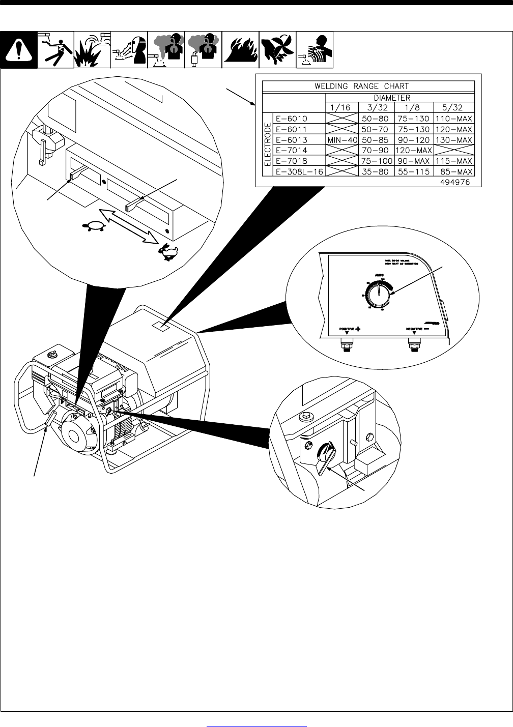
5 Welding Range Label
Use label to determine correct weld amper-
age based on electrode size, type, and mate-
rial thickness.
6 Current Control
Use control to select weld amperage. Control
may be adjusted while welding.
To Set Current Control: Use label to deter-
mine correct size electrode for material thick-
ness. Select electrode type and set current
control to corresponding amperage range.
Adjust control to obtain desired weld
performance.
EXAMPLE:
Material Thickness: 1/8 to 1/4 in
Electrode Diameter: 1/8
Electrode Type: E-6013
Current Control Setting: 90 − 120 A
1
6