


. A complete Parts List is available at www.MillerWelds.com
OM-4434 Page 27
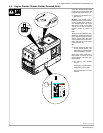
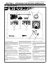
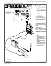
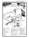
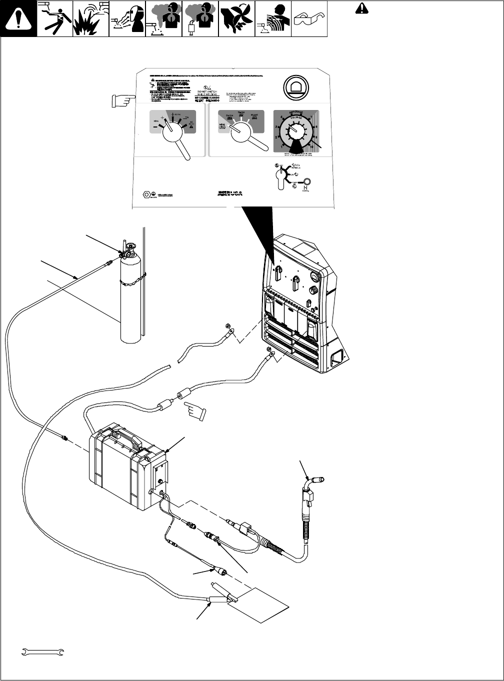
6-4. Typical MIG Welding Connections And Settings
A. Solid Wire Applications
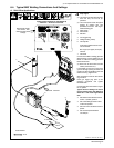
803 847-C / 802 766 / 228 199-A
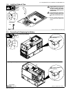
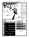
! Stop engine.
. This section provides general guide-
lines and may not suit all ap-
plications.
. The control panel shows the typical
settings for welding with .035
(ER70S-3) solid wire. Use Argon-
based shielding gas.
1 Work Clamp
2 Wire Feeder
3 MIG Gun
4 Gun Trigger Plug
5 Voltage Sensing Clamp
6 Gas Cylinder:
75/25 Argon-Based Gas for Short
Circuit Transfer
80% Argon (Or Higher) For Spray
Transfer
7 Gas Hose
Connect work cable to welding generator
Work terminal. Connect cable from wire
feeder to cable from welding generator
Electrode terminal.
. Be sure to use the correct size weld
cables (see Section 5-7).
Loosen MIG gun securing knob. Insert
gun end through opening in feeder and
position as close as possible to drive rolls
without touching. Tighten knob.
See wire feeder manual for wire thread-
ing procedure.
Insert gun trigger plug (item 4) into
matching receptacle and tighten
threaded collar.
Connect gas hose from feeder to regula-
tor on cylinder.
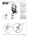
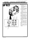
Typical Control Settings For Short
Circuit Transfer Using .035 (ER70S-3)
Solid Wire And 75/25 Argon-Based
Gas:
> Set Weld Process Selector switch
to Wire + (DCEP) position.
> Set Coarse Range switch to Wire
19-28 volts position.
> Set Fine Control to obtain minimum
spatter.
> Set wire feed speed between
150-300 ipm.
Tools Needed:
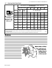
Typical Control Settings For .035 (ER70S-3)
Solid Wire − Short Circuit Transfer
3/4 in
Note Coarse Range,
Fine Control, and
Weld Process switch
settings.
Quick connector
6
3
2
5
1
4
7
Work