


OM-1500-6 Page 10
ST-178 794-A
50/60
S/N:
24
10.0
Hz50/60
IP 21
V100 A750 X 100 %
V
U
1
=
A
I
1
=
1
U
2
=
I
2
=
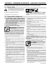
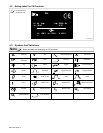
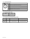
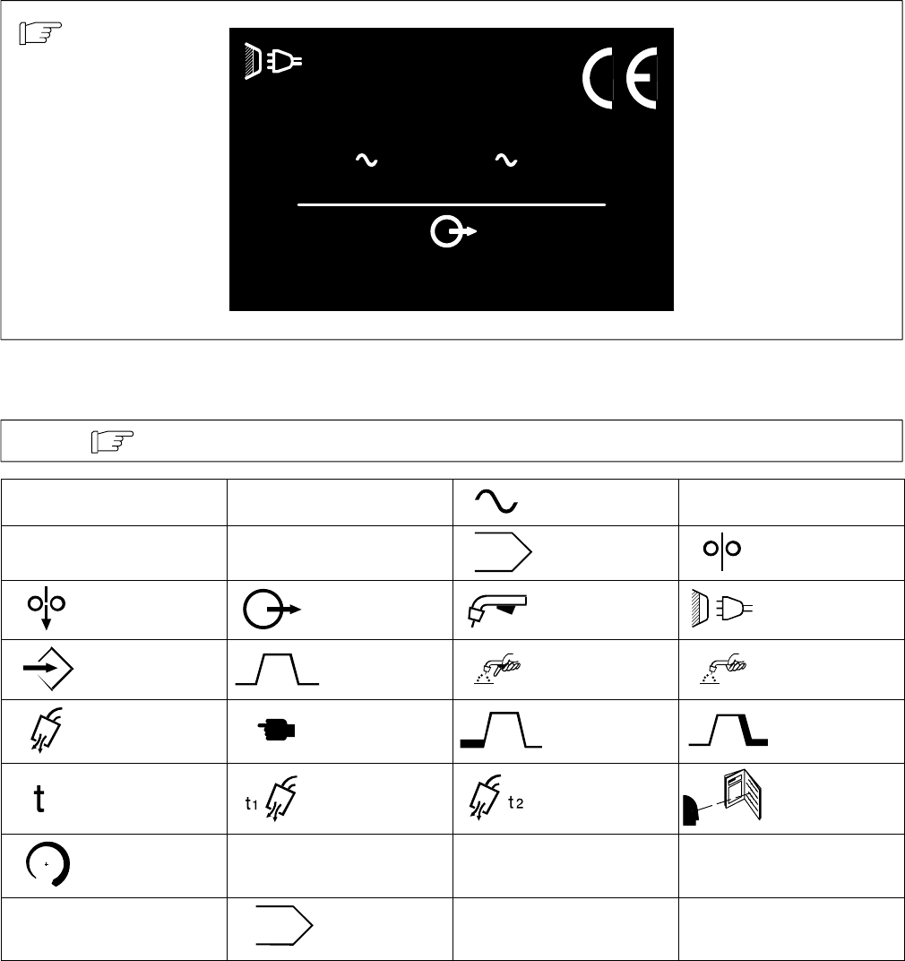
3-2. Rating Label For CE Products
For label location
see Section 5-3.
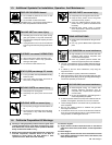
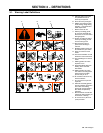
3-3. Symbols And Definitions
Some symbols are found only on CE products.
Note
A
Amperes
V
Volts Alternating Current
X
Duty Cycle
IP
Degree Of
Protection
Hz
Hertz Program Wire Feed
Jog Output Trigger Line Connection
Set Up Sequence Trigger Hold On Trigger Hold Off
Purge Press To Set Start Crater
Time Preflow Time Postflow Time Read Instructions
Increase
I
1
Primary Current
I
2
Rated Current
U
2
Load Voltage
U
1
Primary Voltage
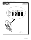
A
B
Dual Schedule