


OM-1500-6 Page 21
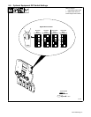
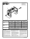
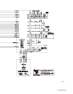
7-2. Diagnostics
803 063-A
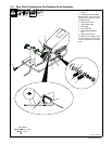
1 LED3 On Right Side Motor
Control Board PC1
2 LED3 On Left Side Motor
Control Board PC101
3 LED3 On Dual Board PC70
2
1
3
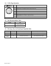
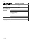
Display On
Optional Meter
LED3 Sequence Indicated Error
Left Side Motor Control
HELP 11 1 Blink Communication Error
Left Side Motor Control
Board PC101
HELP 12 2 Blinks Trigger Error
HELP 13 3 Blinks Tach Error
HELP 14 *4 Blinks Motor Error
Ri
g
ht Side Motor Control
HELP 21 1 Blink Communication Error
Right Side Motor Control
Board PC1
HELP 22 2 Blinks Trigger Error
HELP 23 3 Blinks Tach Error
HELP 24 *4 Blinks Motor Error
Dual Board PC70 HELP 31 *4 Blinks Communication Error
*Since blink On time and blink Off time are equal in a four-blink
cycle, the four−blink sequence appears as constant blinking.
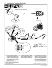
• Error Indications
Error conditions are indicated by LED3 on
PC1, PC101, PC70 or on display if meter op-
tion is present. To view LED3, turn Off unit, re-
move wrapper, and turn unit On. LED3 is most
easily observed from the left side of the unit.
The LED blinks in a 2.5 second cycle. The
number of blinks in this period indicates the
type of error.
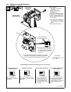
The priority of the errors is related to the num-
ber of blinks indicating the error. The more
blinks, the more severe the error (motor error
is top priority). A higher priority error overrides
a lower one (if a motor error and a communica-
tion error existed, the light would blink four
times for the motor error).
• The communication error occurs 2.5 sec-
onds after a loss of communication between
the motor and the optional meter board or
Dual board. The user may continue to weld
with this error. The error may be cleared by
turning power Off, waiting a minimum of two
seconds, and turning power On.
• The trigger error occurs if the user has the
trigger held for more than two minutes with-
out striking an arc (providing current over-
ride is not enabled), or if the user holds the
trigger past the postflow phase in a timed
weld. This error also occurs if the trigger is
held when the feeder is powered up. The er-
ror may be cleared by releasing the trigger.
• The tach error occurs 2 seconds after the
loss of tachometer feedback. The user may
continue to weld with this error. The motor
speed is regulated through the monitoring of
voltage and current.
• The motor error indicates that the motor
has been drawing too much current for too
long.