


OM-1500-6 Page 32
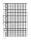
.023-.025 in. 0.6 mm 151 024 087 130
.030 in. 0.8 mm 151 025 053 695
.035 in. 0.9 mm 151 026 053 700 151 036 072 000 151 052 132 958
.045 in. 1.1/1.2 mm 151 027 053 697 151 037 053 701 151 053 132 957 151 070 083 489
.052 in. 1.3/1.4 mm 151 028 053 698 151 038 053 702 151 054 132 956 151 071 083 490
1/16 in.
1.6 mm 151 029 053 699 151 039 053 706 151 055 132 955 151 072 053 708
(.062 in.)
.068-.072 in. 1.8 mm 151 056 132 959
5/64 in.
2.0 mm 151 040 053 704 151 057 132 960 151 073 053 710
(.079 in.)
3/32 in.
(.094 in.)
2.4 mm 151 041 053 703 151 058 132 961 151 074 053 709
7/64 in.
(.110 in.)
2.8 mm 151 042 053 705 132 962 151 075 053 711151 059
1/8 in.
(.125 in.)
3.2 mm 151 043 053 707 151 060 132 963 151 076 053 712
Fraction
Metric
Wire Size V-GROOVE
4 Roll
U-GROOVE VK-GROOVE UC-GROOVE
Drive
Roll
4 Roll Drive
Roll
4 Roll Drive
Roll
4 Roll Drive
Roll
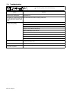
Each Kit Contains An Inlet Guide, Intermediate Guide, And 045 233 Antiwear Guide w/604 612 Setscrew 8-32 x .125, along with 4 Drive Rolls.
Inlet
Guide
150 993
150 993
150 993
150 994
150 994
150 995
150 995
150 995
150 996
150 996
150 997
Intermediate
Guide
149 518
149 518
149 518
149 519
149 519
149 520
149 520
149 520
149 521
149 521
149 522
Kit Kit Kit Kit
.040 in. 1.0 mm 161 190150 993 149 518
Table 9-1. Drive Roll And Wire Guide Kits
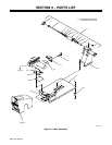
Ref. S-0527-C