


OM-1500-6 Page 16
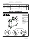
5-8. Setting Internal DIP Switches
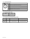
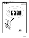
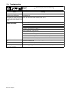
Position Settings And Results For DIP Switch S1 On PC1 And PC101
On = Current detect over-
ride. For welding power
sources that don’t provide
current feedback through
the 14-pin receptacle. Run-
in is inactive.
Off = Current must be detected
from power sources that provide
current feedback through the
14-pin receptacle to go from run-in
to welding condition. Run-in is
active.
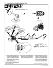
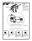
Remove wrapper.
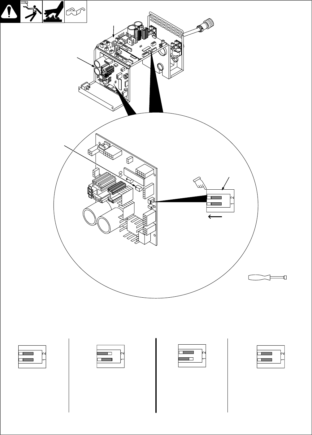
1 DIP Switch S1 On Motor
Board PC1
w Setting Current Detect
Override (S1-1)
Current detect override is used to
disable run-in when a welding pow-
er source is used that doesn’t pro-
vide current feedback through the
14-pin receptacle.
. Pins F & H are not present in 14
pin receptacle on machines
that don’t provide current feed-
back.
Install wrapper when finished.
1
803 063 / Ref. 802 944
. In the DIP switch S1 illustrations,
the elevated slider on each switch
is shown in white. For example,
the switches above are all in the
Off position.
. When DIP switch positions are changed, the unit must be
turned Off and then On again in order for the new settings
to be active. DIP switches are only read on power up.
Tools Needed:
1/4 in
This illustration shows
the factory setting of S1.
S1-1 And S1-2
S1-1 And S1-2
Current Detect Override (ON)
Current Detect Override (OFF)
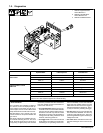
Left Side Motor
Control Board
PC101
Right Side Motor
Control Board PC1
P1
(Factory Default)
On = Run-In speed is
approximately 1/2 weld wire
feed speed.
Off = Run-In speed is set using
potentiometer P1 located on Motor
Board PC1.
S1-1 And S1-2
S1-1 And S1-2
Automatic Run-In (ON)
(Factory Default)
Automatic Run-In (OFF)