


OM-818 Page 11
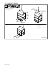
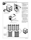
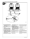
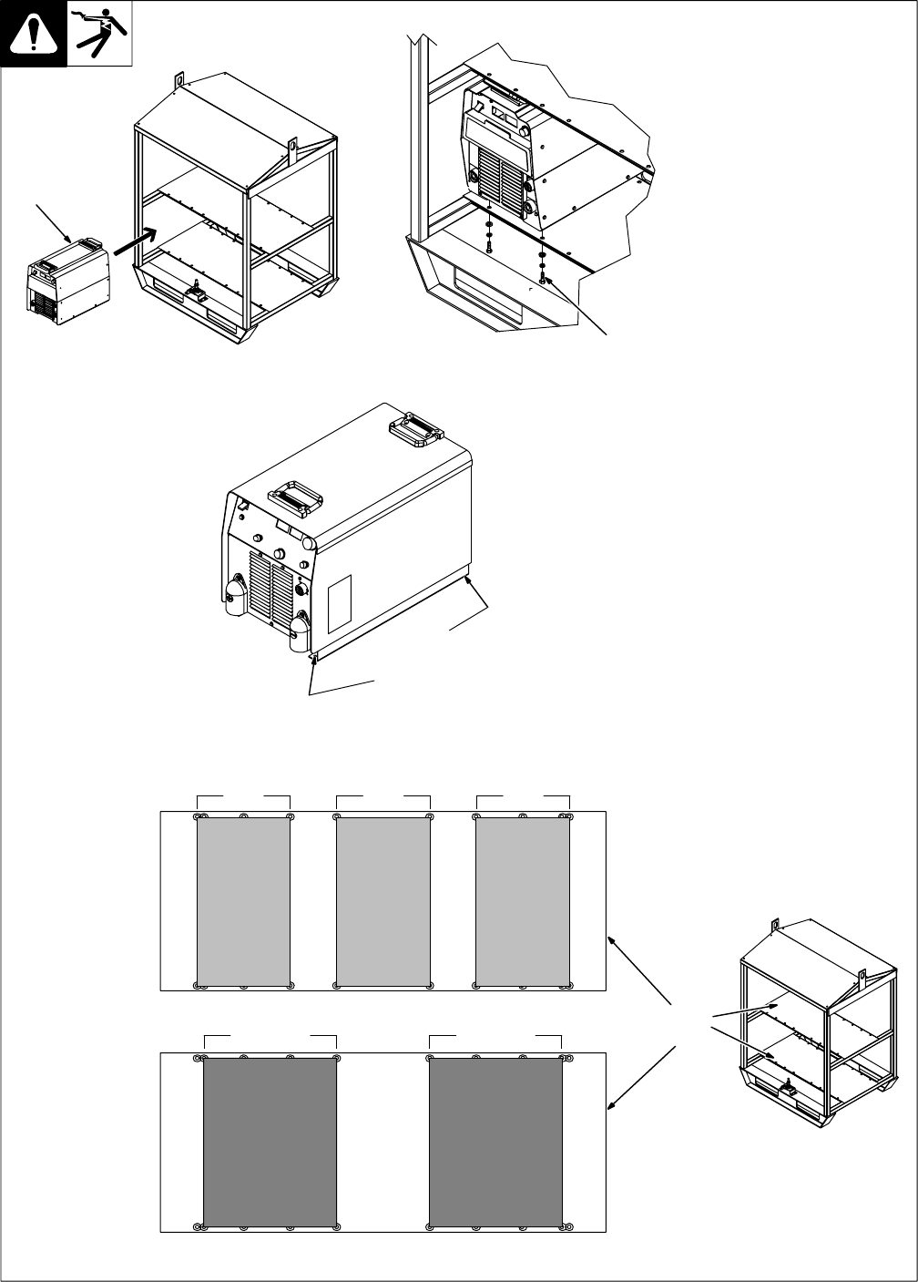
3-4. Installing Welding Power Source Onto Rack
Have only qualified persons make
this installation.
Y Turn Off welding power
sources before inspecting
or installing rack.
For XMT 304/EX 300 Models
1 Welding Power Source
Position welding power source
onto rack shelf so threaded holes in
feet are over correct holes in shelf
on rack (see illustration). Welding
power source front panel should
face side of rack with isolated ter-
minal on base as shown.
2 Securing Bolts And Hardware
Install supplied bolts through rack
shelf into welding power source
feet and tighten.
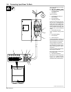
For XMT 456 and Invision 456
Models
1 Welding Power Source
Position welding power source
onto rack shelf so holes in base of
welder align with correct holes in
shelf on rack (see illustration).
Welding power source front panel
should face side of rack with iso-
lated terminal on base as shown.
. The factory-supplied mount-
ing hardware is for XMT
304/EX 300 models only. Do
not attempt to use this hard-
ware when installing an XMT
456 or Invision 456 onto rack.
Install user-supplied 1/4 in mount-
ing bolt through holes in welding
power source base and rack shelf
and tighten user-supplied hard-
ware to secure in place.
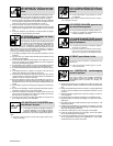
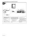
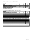
ST-801 192 / ST-801 696 / ST-801 698 / 802 260 / 802 537
1
2
For XMT 304/EX 300 And
XMT 456/Invision 456 Models
For XMT 304/EX 300
Models Only
For XMT 456/Invision 456 Models Only
Location of mounting holes
in bottom of base (both sides).
Mounting Hole
Pattern For
XMT 304/EX 300
Models
(Both Shelves)
Mounting Hole
Pattern For XMT
456/Invision 456
Models
(Both Shelves)
Holes 1 And 4 Holes 5 And 6 Holes 7 And 10
Holes 2 And 5 Holes 6 And 9
Mounting
Shelves