


OM-818 Page 16
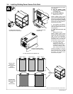
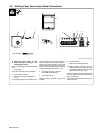
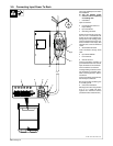
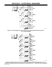
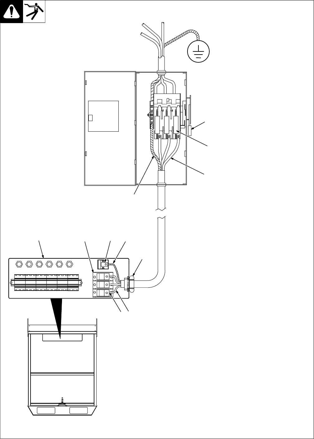
3-9. Connecting Input Power To Rack
Have only qualified persons make
this installation.
Y Turn Off welding power
sources before inspecting
or installing rack.
1 Control Box
Open access door.
2 Line Disconnect Device Of
Proper Rating
3 Input Conductors
4 Grounding Conductor
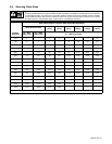
Select size and length using Sec-
tion 3-10 or 3-11. Conductors must
be able to carry the combined am-
perage draw of all welding power
sources mounted on the rack. Con-
ductor insulation must comply with
national, state, and local electrical
codes.
5 Strain Relief Connector
Insert conductors through strain
relief.
6 Input Terminal Block
7 Line Terminals
8 Ground Terminal
Connect grounding conductor to
ground terminal first. Then connect
input conductors to line terminals.
Close control box access door.
Install grounding conductor and in-
put conductors in conduit or equiv-
alent to deenergized line discon-
nect device.
Connect grounding conductor first,
then line input conductors.
Be sure grounding conductor goes
to an earth ground.
9 Overcurrent Protection
Select type and size using Section
3-10 or 3-11. Install into deen-
ergized line disconnect device
(fused disconnect switch shown).
ST-801 702 / Ref. ST-801 703
1
6
8
4
5
2
37
3
4
9