


OM-818 Page 14
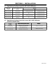
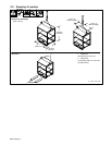
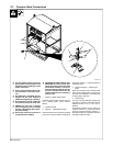
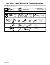
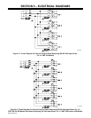
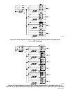
3-7. Common Work Connections
ST-801 700
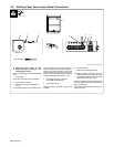
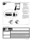
Y Turn Off welding power sources by
placing Power circuit breakers in the
Off position before making any weld
output connections.
Y Do not connect welding output of dif-
ferent polarities to the same struc-
ture.
Y See ANSI Z49.1 and OSHA Title 29,
Chapter XVII, Part 1910, Subpart Q
(addresses at beginning of manual).
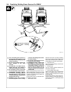
Y Do not handle or come in contact with
two live electrodes at the same time.
Y ARCING can burn skin or damage
electrical equipment. Do not change
position of the welding cable connec-
tors while welding.
Y Be sure the connectors are secure in
receptacles before welding.
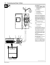
Y INADEQUATE WORK CABLE CON-
NECTIONS can cause serious dam-
age to input power service and create
a hazardous condition. Connect an
electrical cable of adequate size be-
tween the isolated terminal and the
workpiece whenever the isolated ter-
minal is used.
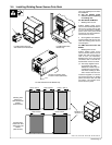
1 Positive (+) Weld Output Cables
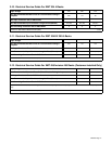
Determine cable lengths and sizes accord-
ing to welding power source Owner’s
Manual.
2 Isolated Terminal
3 Negative (−) Weld Output Cables
Determine cable sizes according to welding
power source Owner’s Manual. Cable must
reach from negative (−) output receptacle to
isolated terminal.
4 Common Negative (−) Weld Output
Cable
Cable must be able to carry combined weld
output of all welding power sources using
common work connections. Use Section 3-6
to select proper cable size.
5 Terminal Lugs
Use lugs of proper amperage capacity and
hole size for connecting to isolated terminal.
Isolated terminal is 1/2 in (12.7 mm) in
diameter.
For Electrode Negative, reverse cable con-
nections. Positive (+) weld output cables
connect to isolated terminal, negative (−)
weld output cables go to electrode. Common
weld output cable is positive.
1
3
4
2
4
5
3
5