


OM-818 Page 12
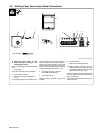
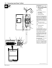
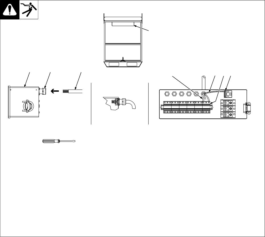
3-5. Welding Power Source Input Power Connections
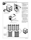
Y Disconnect input power to rack
before working on wiring for any
welding power source.
Have only qualified persons make this instal-
lation.
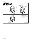
1 Control Box
Open access door on front of control box.
2 Strain Relief Connector
3 Welding Power Source Input Power
Cord
Each welding power source location on the
rack is numbered. The numbers on the con-
trol box access door refer to the similarly lo-
cated strain relief connectors and circuit
breakers inside the control box. Insert power
cord into strain relief with number matching
location of welding power source on rack.
4 Grounding Conductor − Green Or
Green With Yellow Stripe(s)
5 Grounding Terminal
Install grounding conductor to grounding
terminal.
6 Input Conductors
7 Power Circuit Breaker Terminals
. When installing conductors from the
welding power source, torque the Power
circuit breaker terminals and grounding
terminal to 40 in-lbs (4.5 N·m).
Install input conductors from welding power
source to Power circuit breaker nearest entry
for input conductors.
Tighten strain relief connector. Close and se-
cure access door.
Ref. ST-801 703 / ST-801 699
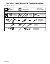
Tools Needed:
1 2 3
6
4 57
1
Side View