


OM-1592 Page 4
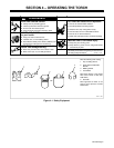
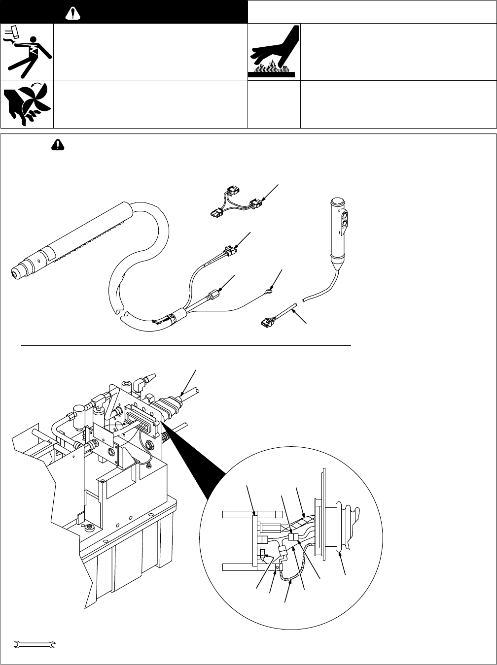
3-2. Installing Machine-Held Torch And Remote Trigger Pendant
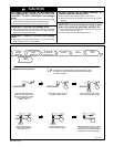
ELECTRIC SHOCK can kill.
• Do not touch live electrical parts.
• Turn Off cutter, and disconnect input power before
installing torch.
MOVING PARTS can cause injury.
• Keep away from moving parts.
HOT PARTS can cause severe burns.
• Allow cooling period before maintaining or servicing.
WARNING
swarn8.1* 10/91
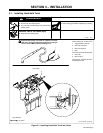
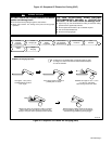
Machine-held torches require a
customer-supplied external switch
or remote trigger control.
Turn Off cutter and remove input
power. Remove top of cutter case.
1 Remote Trigger Leads
2 Strain Relief
3 Boot
Install strain relief in location
shown. Insert leads through boot
and install in strain relief as shown.
Be sure insulation jacket is in strain
relief.
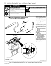
4 Torch Connection Receptacle
5 Gas Hose
6 Pilot Lead
Insert receptacle, hose, and lead
through boot.
7 Pilot Terminal
Connect pilot lead to terminal, and
gas hose to fitting as shown.
8 Printed Circuit Board PC3
9 Three-Way Connector
Connect three-way connector to
matching receptacle on PC3, torch
connection receptacle, and remote
trigger receptacle.
Reinstall top of case.
ST-801 208 / ST-801 202
3/8, 5/8 in
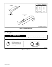
Tools Needed:
1
5
6
Rear Panel
4
3
2
4
1
3
9
5
7
6
8
9
Significant DC voltage can remain on capacitors in cutter
after unit is Off. Always discharge capacitors according to
cutter’s Owner’s Manual before installing torch.
Figure 3-2. Installing Machine-Held Torch And Remote Trigger Pendant Into Cutter