


OM-197 509 Page 7
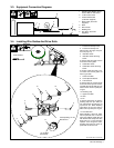
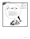
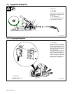
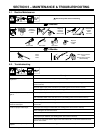
3-3. Equipment Connection Diagrams
1 Deltaship 502 Welding Power
Source With 24 VAC Power
2 10-Pin Control Cord
3 Positive Weld Cable
(Customer Supplied)
4 Work Cable (Customer
Supplied)
5 Work
6 Wire Feeder
7 Welding Gun
8 Gas Hose (Customer
Supplied)
5
3
2
1
6
7
4
8
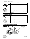
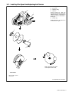
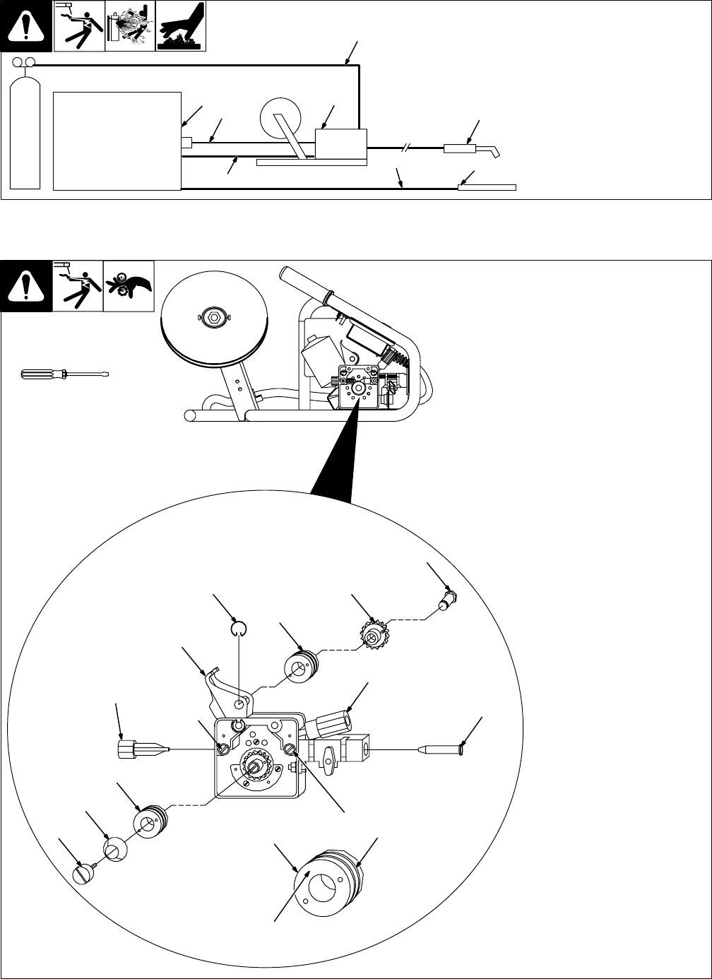
3-4. Installing Wire Guides And Drive Rolls
Ref. ST-802 483-A / ST-802 481
1 Pressure Assembly Knob
2 Pressure Assembly Arm
Move Knob to the right, and pres-
sure arm pops up.
3 Inlet Wire Guide
4 Inlet Wire Guide Securing
Screw
To change inlet wire guide, loosen
screw and remove guide.
5 Outlet Wire Guide
6 Outlet Wire Guide Securing
Screw
To change outlet wire guide, loos-
en screw and remove guide out
front of gun block.
7 Lower Drive Roll
8 Coned Spacer Washer
9 Thumb Screw
To change drive roll, remove thumb
screw and coned spacer washer,
and slide drive roll off shaft. Be sure
holes in drive roll line up with pins
on gear.
10 Retaining Clip
11 Upper Drive Roll
12 Gear
13 Pin
To change upper drive roll, remove
retaining clip from pin. Slide pin
out, and lift drive roll and gear out
of pressure arm. When installing
upper drive roll, be sure holes in
drive roll line up with pins on gear.
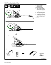
14 Drive Roll Size
When installing a drive roll, either
into the pressure arm or onto the
lower gear adapter, install drive roll
with the wire size stamp of the wire
being used (i.e. 1.2 mm) facing the
operator, even though the corre-
sponding wire groove is on the op-
posite side of the drive roll.
Tools Needed:
4
3
5
7
11
12
13
10
2
1
6
9
8
1.2 mm
Corresponding 1.2 mm
Wire Groove
1.2 mm Wire
Size Stamp
14