


OM-197 509 Page 8
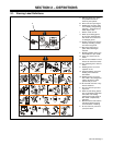
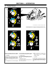
3-5. 10-Pin Plug PLG8 Information
Pin Pin Information
A 24 volts ac for gas valve control when triggered or purging gas.
B +15 volts dc with gun trigger open; 0 volts dc with gun trigger closed.
C Circuit common.
D 0 to +10 volts dc output from min to max of Output Command control R1.
E +10 volts dc input.
F 0 to +10 volts dc output from min to max of Wire Speed control R2
G +15 volts dc with Jog switch S3 open; 0 volts dc with switch closed.
H Motor positive (+), (0 to +24 volts dc input to wire drive motor M1 with respect to pin I.)
I Motor negative (–).
J Not used
3-6. 7-Pin Plug PLG1 Information
Pin Pin Information
1 Not used.
2 Not used.
3 Circuit common.
4 0 to +10 volts dc output from min to max of Output Command control R1.
5 +10 volts dc input.
6 0 to +10 volts dc output from min to max of Wire Speed control R2
197 504
7 +15 volts dc with Jog switch S3 open; 0 volts dc with switch closed.
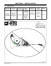
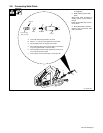
1 Gas Hose (Customer
Supplied)
Connect to gas supply.
2 10 Pin Plug PLG8
Use plug to make connection to
welding power source.
3 Weld Cable w/Quick Connect
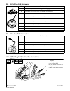
3-7. 10-Pin Plug And Shielding Gas Connections
Ref. St–802 483-A
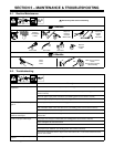
Tools Needed:
1
11/16 in
2
3