


. A complete Parts List is available at www.MillerWelds.com
OM-230 693 Page 16
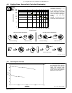
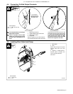
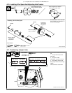
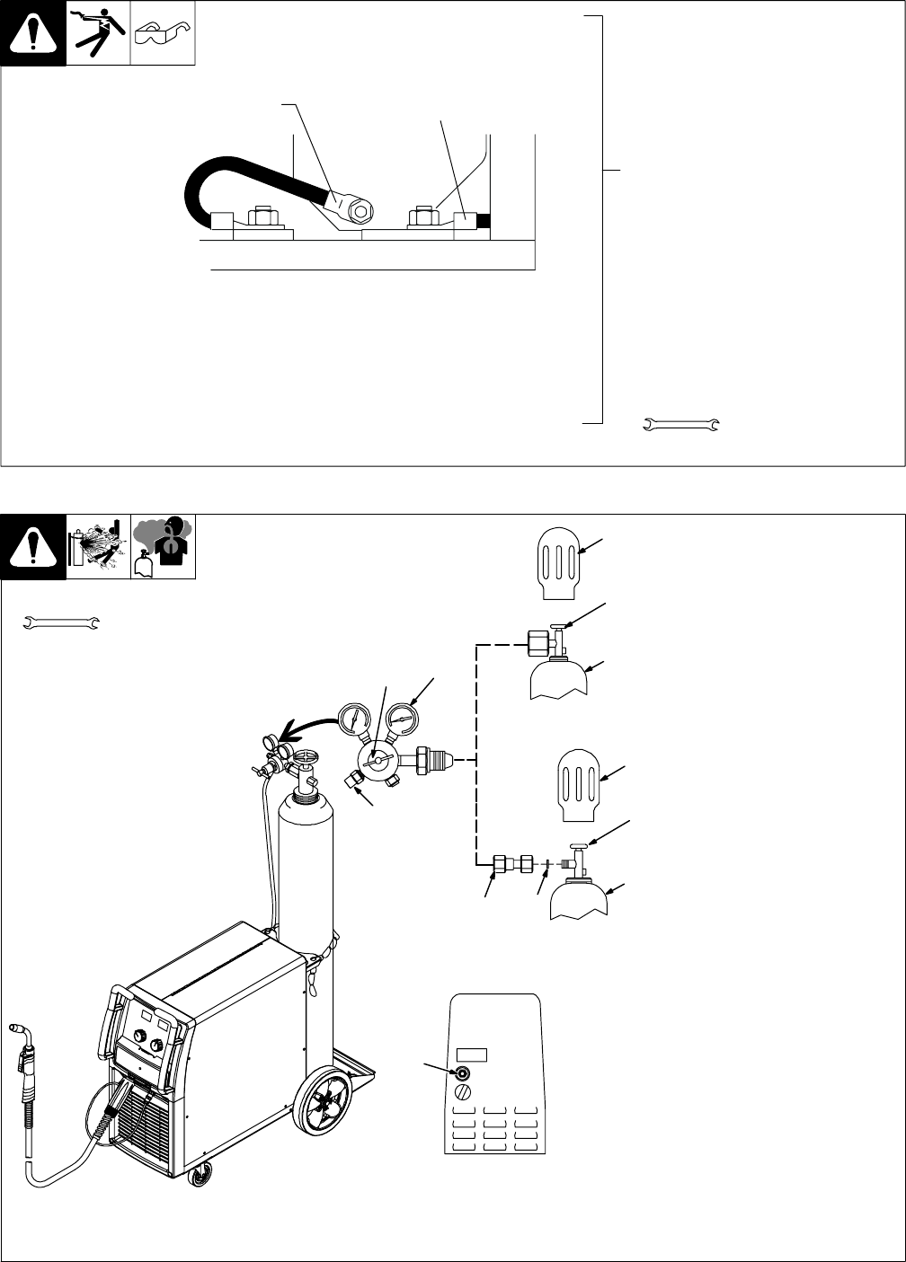
4-8. Setting Gun Polarity For Wire Type
1 Polarity Changeover Label
Information
Always read and follow manufacture’s
recommended polarity.
1
3/4, 11/16 in
Ref. 190 821-A
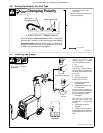
Changing Polarity
D
D
Wire Drive
Assembly Lead
Work Clamp Lead
+
Positive Terminal
Shown as shipped − Electrode Positive (DCEP): For solid steel,
stainless steel, aluminum, or flux core with gas wires (GMAW).
-
Negative Terminal
Electrode Negative (DCEN): Reverse lead connections at
terminals from that shown above for gasless flux core wires
(FCAW). Drive assembly becomes negative.
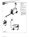
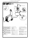
4-9. Installing Gas Supply
Ref. 804 654-A / Ref. 804 912-A
Tools Needed:
Obtain gas cylinder and chain to
running gear, wall, or other
stationary support so cylinder
cannot fall and break off valve.
1 Cap
2 Cylinder Valve
Remove cap, stand to side of
valve, and open valve slightly. Gas
flow blows dust and dirt from valve.
Close valve.
3 Cylinder
4 Regulator/Flowmeter
Install so face is vertical.
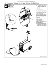
5 Regulator/Flowmeter Gas
Hose Connection
6 Welding Power Source Gas
Hose Connection
Connect customer supplied gas
hose between regulator/flowmeter
gas hose connection, and fitting on
rear of welding power source.
7 Flow Adjust
Typical flow rate is 20 cfh (cubic
feet per hour). Check wire
manufacturer’s recommended
flow rate.
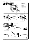
8 CO2 Adapter (Customer
Supplied)
9 O-Ring (Customer Supplied)
Install adapter with O-ring between
regulator/flowmeter and CO
2
cyl-
inder.
1-1/8, 5/8 in
1
2
3
7
Rear Panel
6
4
5
1
2
3
8
9
Argon Gas Or Mixed Gas
CO
2
Gas