


. A complete Parts List is available at www.MillerWelds.com
OM-230 693 Page 29
SECTION 6 − MAINTENANCE &TROUBLESHOOTING
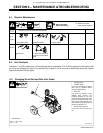
6-1. Routine Maintenance
! Disconnect power
before maintaining.
. Maintain more often
during severe conditions.
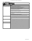
n = Check Z = Change ~ = Clean l = Replace
* To be done by Factory Authorized Service Agent
Reference
Every
3
Months
l Unreadable Labels ~ Weld Terminals nl Weld Cables
Every
6
Months
OR
~ Inside Unit n Apply Light Coat Of Oil
Or Grease To Drive Motor
Shaft
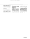
6-2. Unit Overload
Thermistor T in SCR1 protects the unit from damage due to overheating. If HL.P 002 is displayed on the meters, wait
for unit to cool allowing fan motor to run before trying to weld. If unit is cool and no weld output continues, contact
Factory Authorized Service Agent.
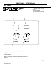
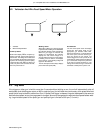
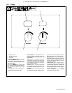
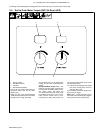
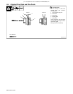
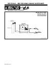
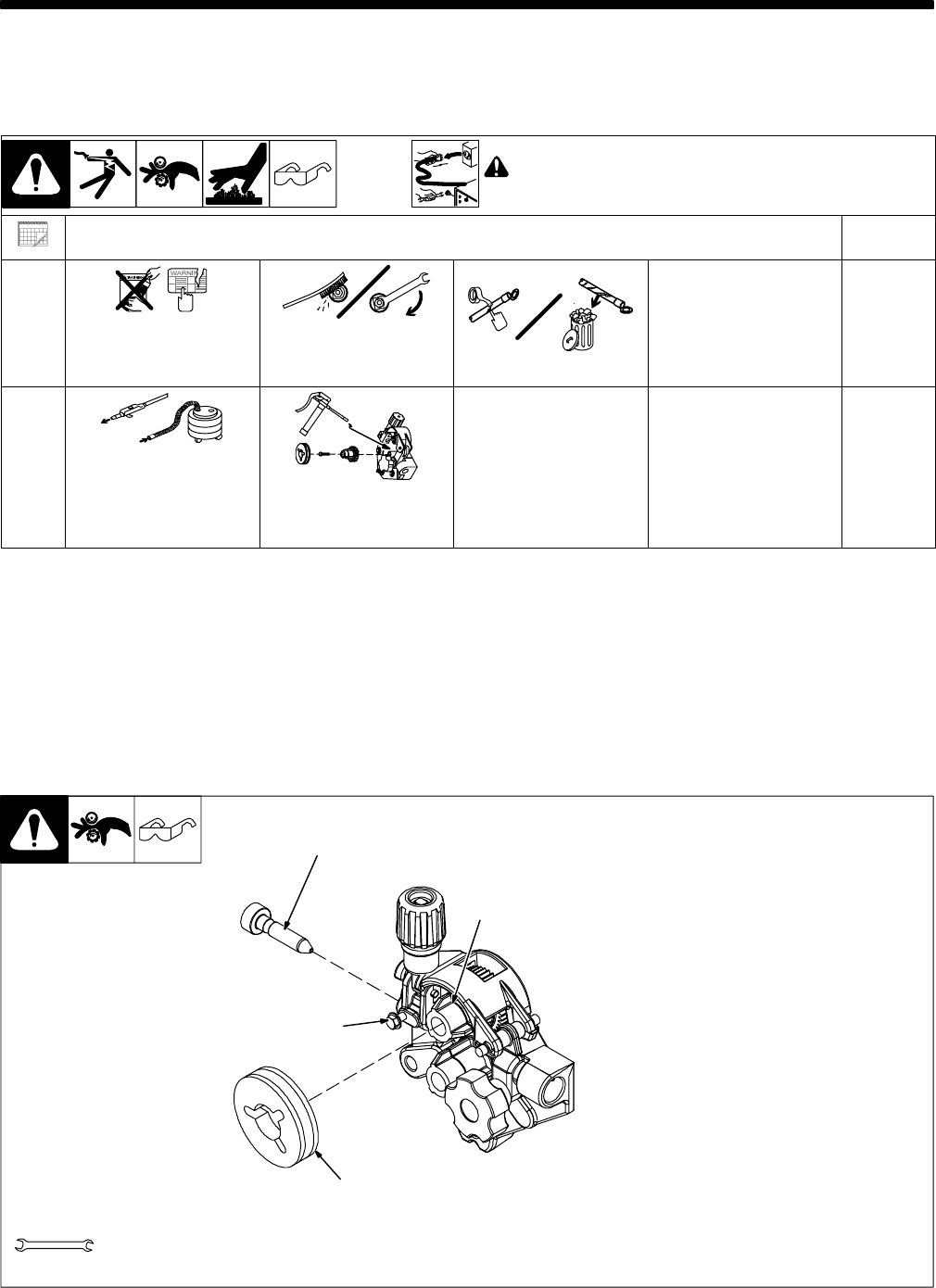
6-3. Changing Drive Roll and Wire Inlet Guide
1 Securing Screw
2 Inlet Wire Guide
Loosen screw. Slide tip as close to
drive rolls as possible without
touching. Tighten screw.
3 Drive Roll
The drive roll consists of two
different sized grooves. The
stamped markings on the end
surface of the drive roll refers to the
groove on the opposite side of the
drive roll. The groove closest to the
motor shaft is the proper groove to
thread (see Section 4-14).
4 Drive Roll Securing Nut
Turn nut one click to secure drive
roll.
Tools Needed:
7/16 in
1
2
3
4
Ref. 804 914-A