


. A complete Parts List is available at www.MillerWelds.com
OM-230 693 Page 19
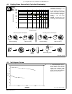
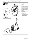
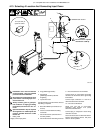
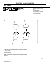
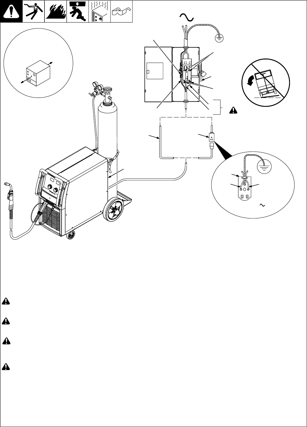
4-13. Selecting A Location And Connecting Input Power
804 912-A
L1L2
230 VAC, 1
18 in (457 mm) of
space for airflow
! Do not move or operate
unit where it could tip.
3
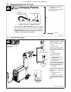
! Installation must meet all National
and Local Codes − have only qualified
persons make this installation.
! Disconnect and lockout/tagout input
power before connecting input con-
ductors from unit.
! Always connect green or green/yel-
low conductor to supply grounding
terminal first, and never to a line ter-
minal.
! Special installation may be required
where gasoline or volatile liquids are
present − see NEC Article 511 or CEC
Section 20.
1 Rating Label
Supply correct input power.
2 Plug (NEMA Type 6-50P)
3 Receptacle
[NEMA Type 6-50R (Customer
Supplied)]
4 Input Power Cord.
Connect directly to line disconnect device if
hard wiring is required.
5 Black And White Input Conductor (L1
And L2)
6 Green Or Green/Yellow Grounding
Conductor
7 Disconnect Device (switch shown in
the OFF position)
8 Disconnect Device Grounding Terminal
9 Disconnect Device Line Terminals
Connect green or green/yellow grounding
conductor to disconnect device grounding
terminal first.
Connect input conductors L1 and L2 to
disconnect device line terminals.
10 Over-Current Protection
Select type and size of over-current
protection using Section 4-12 (fused
disconnect switch shown).
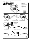
Connect plug to receptacle if hard wiring
method is not used.
Close and secure door on disconnect device.
Remove lockout/tagout device, and place
switch in the On position.
1
2
4
1
=GND/PE Earth Ground
7
L1
L2
6
5
8
9
10