


4
5
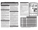
Grounded tools require a three wire extension
cord. Double insulated tools can use either a two
or three wire extension cord. As the distance from
the supply outlet increases, you must use a heavier
gauge extension cord. Using extension cords with
inadequately sized wire causes a serious drop in
voltage, resulting in loss of power and possible tool
damage. Refer to the table shown to determine the
required minimum wire size.
The smaller the gauge number of the wire, the
greater the capacity of the cord. For example, a 14
gauge cord can carry a higher current than a 16
gauge cord. When using more than one extension
cord to make up the total length, be sure each cord
contains at least the minimum wire size required. If
you are using one extension cord for more than one
tool, add the nameplate amperes and use the sum
to determine the required minimum wire size.
Guidelines for Using Extension Cords
• If you are using an extension cord outdoors,
be sure it is marked with the suffi x “W-A” (“W”
in Canada) to indicate that it is acceptable for
outdoor use.
• Be sure your extension cord is properly wired
and in good electrical condition. Always replace
a damaged extension cord or have it repaired by
a qualifi ed person before using it.
• Protect your extension cords from sharp objects,
excessive heat and damp or wet areas.
READ AND SAVE ALL
INSTRUCTIONS FOR FUTURE USE.
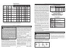
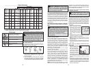
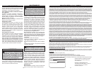
Recommended Minimum Wire Gauge
for Extension Cords*
Extension Cord Length
* Based on limiting the line voltage drop to fi ve volts
at 150% of the rated amperes.
Nameplate
Amperes
0 - 2.0
2.1 - 3.4
3.5 - 5.0
5.1 - 7.0
7.1 - 12.0
12.1 - 16.0
16.1 - 20.0
25'
18
18
18
18
16
14
12
75'
18
18
16
14
12
10
100'
18
16
14
12
10
150'
16
14
12
12
50'
18
18
18
16
14
12
10
EXTENSION CORDS
ASSEMBLY
WARNING To reduce the risk of injury,
always unplug tool before attaching
or removing accessories or making adjust-
ments. Use only specifi cally recommended
accessories. Others may be hazardous.
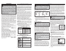
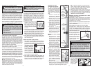
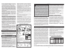
Grounded Tools: Tools with Three Prong Plugs
Tools marked “Grounding Required” have a three
wire cord and three prong grounding plug. The
plug must be connected to a properly grounded
outlet (See Figure A). If the tool should electrically
malfunction or break down, grounding provides a
low resistance path to carry electricity away from
the user, reducing the risk of electric shock.
The grounding prong in the plug is connected
through the green wire inside the cord to the
grounding system in the tool. The green wire in the
cord must be the only wire connected to the tool's
grounding system and must never be attached to
an electrically “live” terminal.
Your tool must be plugged into an ap-
propriate outlet, properly installed and
grounded in accordance with all codes
and ordinances. The plug and
outlet should look like those in
Figure A.
Double Insulated Tools:
Tools with Two Prong Plugs
Tools marked “Double Insulated” do not require
grounding. They have a special double insula-
tion system which satisfi es OSHA requirements
and complies with the applicable standards of
Underwriters Laboratories, Inc.,
the Canadian Standard Asso-
ciation and the National Elec-
trical Code. Double Insulated
tools may be used in either of
the 120 volt outlets shown in
Figures B and C.
Fig. B
Fig. C
Fig. A
GROUNDING
WARNING Improperly connecting the
grounding wire can result in the risk of
electric shock. Check with a qualifi ed electri-
cian if you are in doubt as to whether the
outlet is properly grounded. Do not modify
the plug provided with the tool. Never remove
the grounding prong from the plug. Do not
use the tool if the cord or plug is damaged. If
damaged, have it repaired by a MILWAUKEE
service facility before use. If the plug will not
fi t the outlet, have a proper outlet installed by
a qualifi ed electrician.
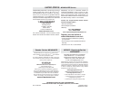
Removing and Replacing Quik-Lok
®
Cords
MILWAUKEE's exclusive Quik-Lok
®
Cords provide
instant fi eld replacement or substitution.
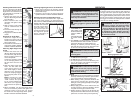
1. To remove the Quik-Lok
®
Cord, turn the cord nut
1/4 turn to the left and pull it out.
2. To replace the Quik-Lok
®
Cord, align the connec-
tor keyways and push the connector in as far as
it will go. Turn the cord nut 1/4 turn to the right
to lock.
Installing Side Handle
MILWAUKEE D-Handle Drills are supplied with a
side handle that can be installed on either side of
the tool for right or left handed use. To install the
side handle, attach the side handle to the extension.
Thread it into the socket on the desired side of the
tool and tighten it securely. Because of the high
torque of this drill, the side handle must always be
used when operating the drill.
WARNING To reduce the risk of
injury, always use a side handle when us-
ing this tool. This tool operates with high
torque. Always brace or hold the tool securely.
WARNING When using the D-handle
drill without the right angle drive unit, do
not clamp the ring clamp with attached side
handle to the front of the gear case; use the
side handle instead.
Do not use the extension when using the
ring clamp.
For D-handle drill without Right Angle Drive Unit:
When using the D-handle drill without the right an-
gle drive unit, remove the ring clamp with attached
side handle, then remove the side handle from the
ring clamp. Attach the side handle to the extension.
The side handle can be installed on either side of
the tool for right or left handed use. To install the
extension with attached side handle, thread it into
the socket on the desired side of the tool (for right
or left-handed use) and tighten securely.
NOTE: If you have an extra ring clamp with at-
tached side handle and extension with attached
side handle, do not use the extension with attached
side handle when using the right angle drive unit.
Remove it from the tool.
Symbology
Volts Alternating Current
No Load Revolutions per
Minute (RPM)
Amperes
Mexican Approvals Marking
Underwriters Laboratories, Inc.,
United States and Canada
Ring Clamp, Extension, and Side Handle for
Right Angle Drive Unit
For D-handle drill with Right Angle Drive Unit:
A ring clamp, extension, and side handle are sup-
plied with the Right Angle Drive Unit. When using a
right angle drive unit, attach the side handle to the
ring clamp. Do not use the extension when using
the ring clamp. The ring clamp with attached side
handle clamps onto the right angle drive unit and
can swivel 360° and locked tight in any position.
WARNING To prevent personal injury,
always remove the chuck key from the chuck
after each use.
Chuck jaws
Chuck key hole
Installing Bits into Keyed Chucks
Be sure that the shank of the bit and the chuck jaws
are clean. Dirt particles may cause the bit to line up
improperly. Do not use bits larger than the maxi-
mum recommended capacity of the drill because
gear damage or motor overloading may result. For
best performance, be sure that the bits are properly
sharpened before use.
1. Unplug the tool.
2. Open the chuck jaws wide
enough to insert a bit. Allow
the bit to strike the bottom of
the chuck. Center the bit in
the chuck jaws and tighten
the jaws by hand to align the bit.
3. Place the chuck key into each of the three holes
in the chuck, turning it clockwise to tighten the
chuck securely.
NOTE: Never use a wrench or means other than
a chuck key to tighten or loosen the chuck.
4. To remove the bit, insert the chuck key into one
of the holes in the chuck and turn it counterclock-
wise.
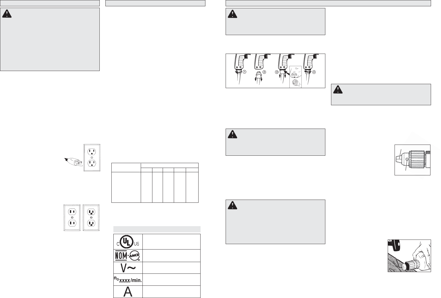
Removing the Chuck from the Drill
1. To remove the left-hand screw inside the chuck,
unplug the tool and open the chuck jaws. In-
sert a T-handle hex key
into the screw inside the
chuck. Turn the T-handle
hex key and remove the
screw. Save the screw
for installing your new
chuck.
2. To remove chuck; tighten a large hex key into
the chuck. Place the chuck on a workbench as
shown. Strike the hex key with a soft-headed
mallet to loosen the chuck. Remove the chuck
by hand.