


20
21
Fig. B
Fig. C
Fig. A
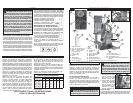
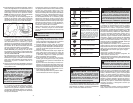
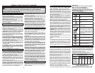
GROUNDING
Grounded Tools: Tools with Three Prong Plugs
Tools marked “Grounding Required” have a three
wire cord and three prong grounding plug. The
plug must be connected to a properly grounded
outlet (See Figure A). If the tool should electrically
malfunction or break down, grounding provides a
low resistance path to carry electricity away from
the user, reducing the risk of electric shock.
The grounding prong in the plug is connected
through the green wire inside the cord to the
grounding system in the tool. The green wire in the
WARNING Improperly connecting the
grounding wire can result in the risk of elec-
tric shock. Check with a qualifi ed electrician
if you are in doubt as to whether the outlet is
properly grounded. Do not modify the plug
provided with the tool. Never remove the
grounding prong from the plug. Do not use
the tool if the cord or plug is damaged. If
damaged, have it repaired by a MILWAUKEE
service facility before use. If the plug will not
fi t the outlet, have a proper outlet installed by
a qualifi ed electrician.
cord must be the only wire connected to the tool's
grounding system and must never be attached
to an electrically “live” terminal. Your tool must be
plugged into an appropriate outlet,
properly installed and grounded in
accordance with all codes and ordi-
nances. The plug and outlet should
look like those in Figure A.
Double Insulated Tools: Tools with Two Prong Plugs
Tools marked “Double Insulated” do not require
grounding. They have a special double insulation
system which satisfi es OSHA requirements and
complies with the applicable standards of Underwrit-
ers Laboratories, Inc., the Cana-
dian Standard Association and the
National Electrical Code. Double
Insulated tools may be used in ei-
ther of the 120 volt outlets shown in
Figures B and C.
In specifi c countries, double insulated tools could
be used in the out-
put connections suit-
able for the plug.
21
20
19
18
22
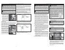
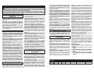
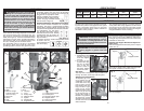
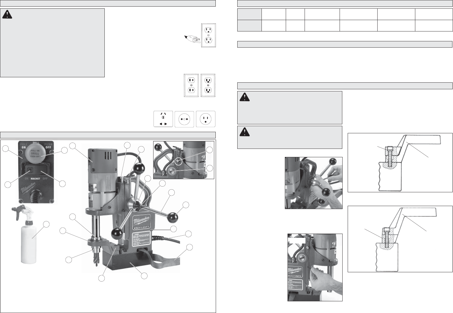
1. Drill motor
2. Slide
3. Wrench storage
(includes 3/32" and
3/16" hex keys)
4. Stop knob
5. Pinion
6. Hub
7. Handle screw
14
9
11
12
10
13
16
15
7
17
1
8. Feed handle
9. Grip
10. Housing
11. Cord
12. Safety strap
13. Magnetic base
14. Spacer
15. Drill spindle
16. Support bracket
17. Cutting fl uid reservoir
18. Control panel
19. Magnet indicator light
20. Magnet switch
21. Drill on/off switch
22. Hand pump
2
3
4
5
8
6
FUNCTIONAL DESCRIPTION
ASSEMBLY
WARNING To reduce the risk of injury,
always unplug tool before attaching or remov-
ing accessories or making adjustments. Use
only specifi cally recommended accessories.
Others may be hazardous.
WARNING To reduce the risk of injury,
wear safety goggles or glasses with side
shields.
Line Lockout
The line lockout prevents the drill motor from start-
ing when line power is fi rst applied to the system
or after a momentary power loss. To reset tool,
turn magnet switch to "OFF" position and drill on/
off switch to "OFF" position.
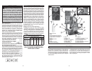
FEATURES
Cat. No. Volts AC W No Load RPM
Arbor
Bore
*Twist
Drill
HSS
Cutter
4270-59
4270-59A
220-240
220-240
1050
1050
450
450
19 mm (3/4")
19 mm (3/4")
13 mm (1/2")
13 mm (1/2")
38 mm (1-1/2")
38 mm (1-1/2")
* Requires use of 1/2" drill chuck adapter
SPECIFICATIONS
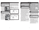
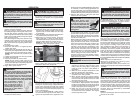
Attaching Feed Handles and Grips
1. Assemble the feed
handles and grips
to the hub. Tighten
securely.
2. To mount the hub
to either side, align
the two (2) dowel
pins on the hub
with the holes in
the pinion. Tighten
the handle screw.
Fig. 1
Fig. 4
Support bracket
Spacer
When using 2" depth cutters, install support bracket
with spacer on bottom, as shown in Fig. 4.
Stop Knob
The stop knob is designed to stop the slide from
moving. To install, screw stop knob into place.
Adjusting the Gib Assembly
To adjust the gib, loos-
en or tighten the gib
adjustment set screws
on the side of the sup-
port housing accord-
ingly with the 3/32" hex
key provided. Tight-
ening the set screws
increases friction on the
slide. The gib should
be set tight enough to
support the weight of
the drill in any position.
All adjusting screws
should be set to provide
smooth and even travel over the entire length of
slide movement.
Fig. 2
The set screws contain a nylon patch that prevents
them from moving freely. Additional adjustment
of the gib may be required from time to time with
extended use of the tool.
Adjusting the Support Bracket and Spacer for
Depth of Cut
This unit is shipped from the factory set for 1" depth
cutters (Fig. 3).
Fig. 3
Support bracket
Spacer
NOTE: Do not use a spacer and support bracket
with chuck adapter.
Motor/Magnet Interlock
The motor/magnet interlock is a feature that pre-
vents power from being applied to the drill motor
if the magnet is not energized. The motor magnet
interlock also prevents the magnet from being de-
energized while the motor is running.