


4 5
8. Never use dull or damaged bits. Sharp
bits must be handled with care. Dam-
aged bits can break during use. Dull bits
require more force to push the tool, which
could cause the bit to break. Damaged
bits can throw carbide pieces and burn
the workpiece.
9. After changing the bit or making any
adjustments, make sure the collet
nut and any other adjustment de-
vices are securely tightened. Loose
adjustment devices can unexpectedly
shift, causing loss of control. Loose
rotating components will be violently
thrown. Watch for vibration or wob-
bling that could indicate an improperly
installed bit.
10. Maintain fi rm grip on router when start-
ing motor to resist starting torque.
11. Always keep the power supply cord
away from moving parts on the tool.
Keep the cord away from the direction of
the cut.
12. Never start the tool when the bit is in
contact with the material. The bit cut-
ting edge may grab the material causing
loss of control of the tool.
13. Never lay the tool down until the bit
has come to a complete stop. The
spinning bit can grab the surface and pull
the tool out of your control.
14. Never touch the bit during or immedi-
ately after use. After use the bit may be
hot enough to burn bare skin.
15. Use clamps or another practical way
to secure and support the workpiece
to a stable platform. Holding the work
by hand or against your body leaves it un-
stable and may lead to loss of control.
16. Never clamp the workpiece to a hard
surface, such as concrete or stone.
Contact with the bit could cause the tool
to jump and loss of control.
17. Only operate the routers when held.
Do not clamp or secure the router to
a surface and hold the workpiece by
hand.
18. Never use bits larger than the smallest
of the openings in the base, sub-base,
or dust collection port.
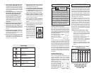
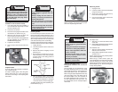
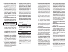
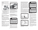
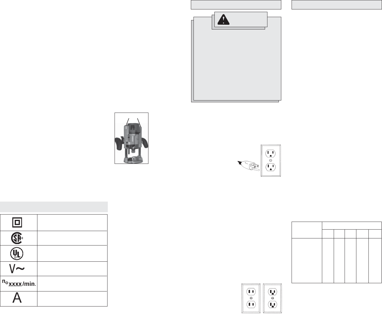
19. Do not loosen or
remove the plunge
base caps. Internal
springs are under
pressure. If loos-
ened or removed, the
plunge base caps and
internal springs will
become projectiles,
which could cause
injury.
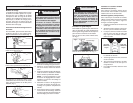
Amperes
Double Insulated
Symbology
Canadian Standards
Association
Underwriters
Laboratories, Inc.
Volts Alternating Current
No Load Revolutions
per Minute (RPM)
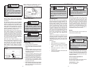
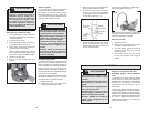
The grounding prong in the plug is connected
through the green wire inside the cord to the
grounding system in the tool. The green wire
in the cord must be the only wire connected
to the tool's grounding system and must never
be attached to an electrically “live” terminal.
Your tool must be plugged into an appropri-
ate outlet, properly installed and grounded in
accordance with all codes and ordinances.
The plug and outlet should look like those
in Figure A.
Double Insulated Tools:
Tools with Two Prong Plugs
Tools marked “Double Insulated” do not
require grounding. They have a special
double insulation system which satisfies
OSHA requirements and complies with the
applicable standards of Underwriters Labo-
Grounded Tools:
Tools with Three Prong Plugs
Tools marked “Grounding Required” have a
three wire cord and three prong grounding
plug. The plug must be connected to a prop-
erly grounded outlet (See Figure A). If the tool
should electrically malfunction or break down,
Fig. B Fig. C
Fig. A
Improperly connecting the grounding
wire can result in the risk of electric
shock. Check with a qualifi ed electri-
cian if you are in doubt as to whether
the outlet is properly grounded. Do not
modify the plug provided with the tool.
Never remove the grounding prong
from the plug. Do not use the tool if the
cord or plug is damaged. If damaged,
have it repaired by a MILWAUKEE ser-
vice facility before use. If the plug will
not fi t the outlet, have a proper outlet
installed by a qualifi ed electrician.
GROUNDING
WARNING
grounding provides a
low resistance path to
carry electricity away
from the user, reduc-
ing the risk of electric
shock.
ratories, Inc., the Cana-
dian Standard Associa-
tion and the National
Electrical Code. Double
Insulated tools may be
used in either of the 120
volt outlets shown in
Figures B and C.
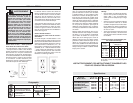
Grounded tools require a three wire extension
cord. Double insulated tools can use either
a two or three wire extension cord. As the
distance from the supply outlet increases,
you must use a heavier gauge extension cord.
Using extension cords with inadequately sized
wire causes a serious drop in voltage, result-
ing in loss of power and possible tool damage.
Refer to the table shown to determine the
required minimum wire size.
The smaller the gauge number of the wire,
the greater the capacity of the cord. For
example, a 14 gauge cord can carry a higher
current than a 16 gauge cord. When using
more than one extension cord to make up
the total length, be sure each cord contains
at least the minimum wire size required. If
you are using one extension cord for more
than one tool, add the nameplate amperes
and use the sum to determine the required
minimum wire size.
Guidelines for Using Extension Cords
• If you are using an extension cord out-
doors, be sure it is marked with the suffi x
“W-A” (“W” in Canada) to indicate that it
is acceptable for outdoor use.
• Be sure your extension cord is prop-
erly wired and in good electrical
condition. Always replace a damaged
extension cord or have it repaired by a
qualifi ed person before using it.
• Protect your extension cords from sharp
objects, excessive heat and damp or wet
areas.
READ AND SAVE ALL
INSTRUCTIONS FOR
FUTURE USE.
Recommended Minimum Wire Gauge
for Extension Cords*
Extension Cord Length
* Based on limiting the line voltage drop to
fi ve volts at 150% of the rated amperes.
Nameplate
Amperes
0 - 2.0
2.1 - 3.4
3.5 - 5.0
5.1 - 7.0
7.1 - 12.0
12.1 - 16.0
16.1 - 20.0
25'
18
18
18
18
16
14
12
75'
18
18
16
14
12
10
100'
18
16
14
12
10
150'
16
14
12
12
50'
18
18
18
16
14
12
10
EXTENSION CORDS
Plunge Base Caps